
EVPN-VXLAN Multi-Tenant Data Center Network with BGP
Published:
Network Architecture Overview
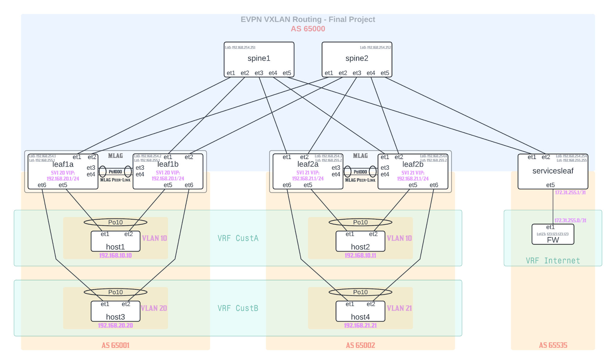 Figure 1
AS 65000 (Core Spine Layer):
Two spine switches (spine1, spine2) providing redundant core connectivity
Each spine has 5 interfaces (et1-et5) for leaf connections
AS 65001 (Left Customer Site):
Two leaf switches (leaf1a, leaf1b) in MLAG configuration
Hosts customer VRFs: VRF CustA and VRF CustB
Host connectivity: host1 (VLAN 10) and host3 (VLAN 20)
AS 65002 (Right Customer Site):
Two leaf switches (leaf2a, leaf2b) in MLAG configuration
Hosts customer VRFs: VRF CustA and VRF CustB
Host connectivity: host2 (VLAN 10) and host4 (VLAN 21)
AS 65535 (Services/Internet):
Single services leaf for external connectivity (simulated by multiple loopback interfaces on FW)
Firewall in VRF internet
Project Task Overview
Progress and expand the previous project work into an L3 leaf/spine network in ContainerLab Studio with 2 spines, 2x2 compute leafs in MLAG and 1x1 service leaf (standalone; not in MLAG); implement symmetrical EVPN VXLAN IRB (Integrated Routing and Bridging) through CLI; CustA hosts should only be able to ping each other; CustB hosts should be able to ping each others and external hosts provided through the simulated “external” connectivity over the service leaf; in other words, CustA hosts do not have access to the Internet VRF, only CustB hosts do; respect the topology as verbatim as possible; pay attention to details and to enable two-way routing information import/export RTs where needed; VRF boxed markings on the topology indicate hosts and FW VRF membership (not that the configuration of the VRF should take place on those devices, but rather on the leaf devices exclusively); create a number of loopback interfaces on the FW itself with simulated external IPs and advertise reachability to them to the service leaf via iBGP; ensure that on all the hosts and the FW you have Ma0 interface moved into the MGMT VRF, so that you can create a default route on hosts and the FW; also advertise the default route from the FW to the service leaf; take into the account all design considerations for such a setup.
Underlay Network configuration
Assigning IP addresses to Interfaces for Spine-Leaf connectivity
We have to enable ip routing on all Leaf and spines so that they can listen for incoming traffic and route it.
We create Point-to-point (/31) links between spine and leaf switches that use IP addressing from the 192.168.0.0/24 subnet.
All the interfaces are configured as no switchport making them L3 links.
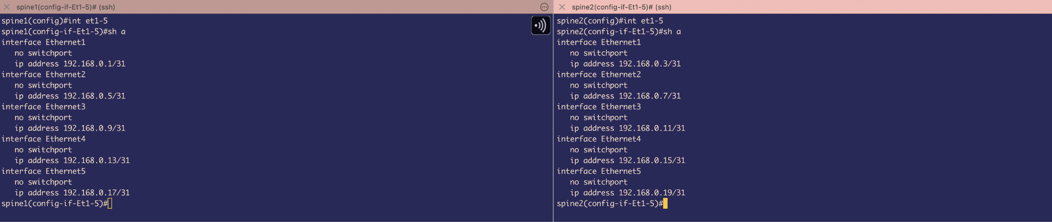 Figure 2
IP address on interfaces of Spines
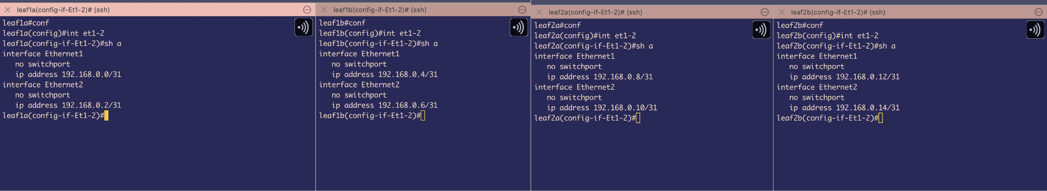 Figure 3
IP address on interfaces of Leafs
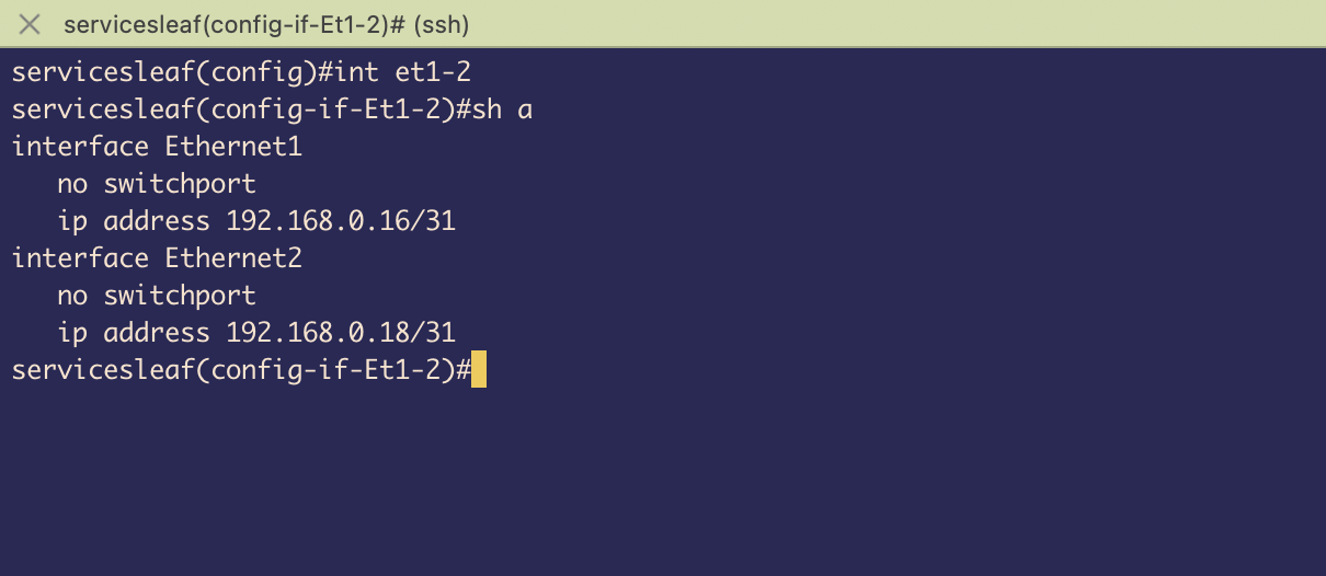 Figure 4
IP address on interfaces of Service Leaf
MLAG configuration on Leafs (Leaf1A&B and Leaf2A&B)
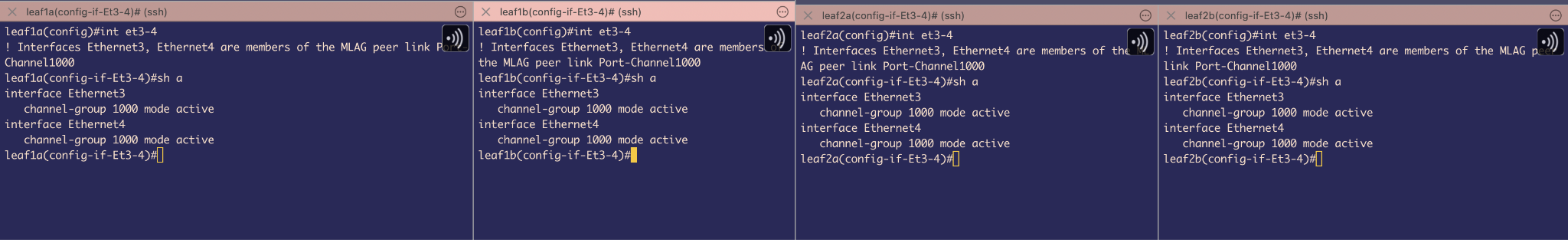 Figure 5
Port-channel 1000 is configured as the MLAG peer-link using Ethernet interfaces 3 and 4. Both interfaces are assigned to channel-group 1000 in LACP active mode, enabling automatic bundle negotiation and system-ID synchronization between MLAG peers.
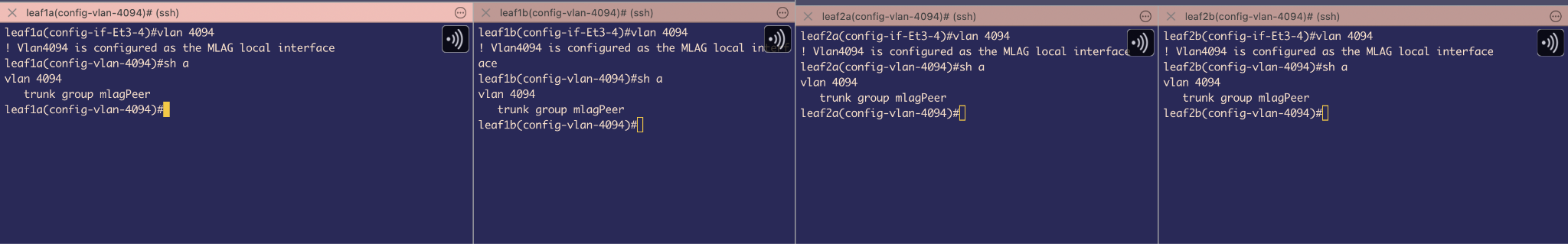 Figure 6
Created VLAN 4094 and included it in a Trunk group MlagPeer –to exclude VLAN 4094 from other MLAG member ports. If any other interface is trunk and allows VLAN 4094 , it still does not send traffic because we still need to add that group to the interface. - it’s like a safety measure.
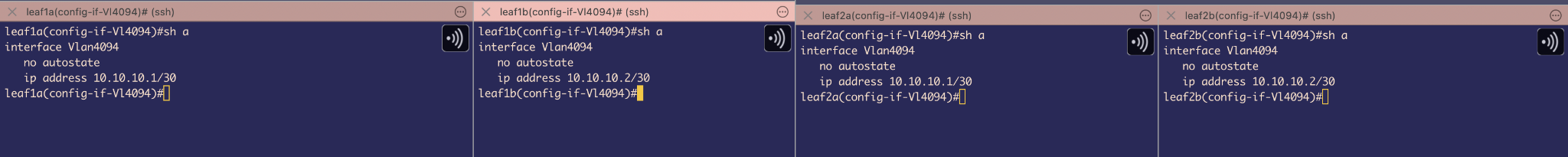 Figure 7
Created SVI for VLAN 4094 and assigned it IP address in subnet 10.10.10.0/30 –MLAG uses this SVI to establish a TCP connection to communicate with its peer to maintain synchronization with its peer (for example, by sending MAC SYNC packets) .
We also used no autostate command because we want the SVI to be up regardless of the state of the physical interfaces
Also, we have to exclude VLAN 4094 from Spanning-tree participation using no spanning-tree vlan-id 4094 (Even though our switches run MSTP which is not VLAN based , but as a safety measure, we will disable VLAN 4094 from ever taking part in STP convergence even if there is PVSTP interoperability scenario )
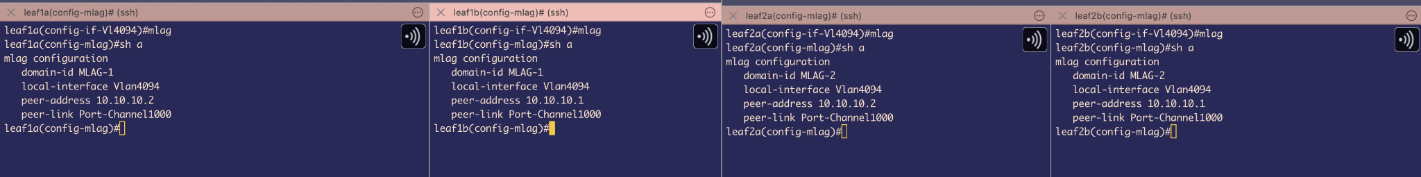 Figure 8
Finally, under mlag , we assigned it a domain-id , local-interface which is SVI4094 and peer device’s IP address and which port-channel is being used as our Peer-link
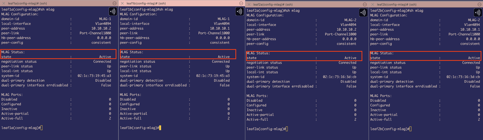 Figure 9
Show mlag command can be used to check MLAG status
It shows the state is Active that means MLAG has been configured properly on all leafs
Leaf 1A and 1B = 1 logical MLAG switch
Leaf 2A and 2B = 1 logical MLAG switch
Host configuration & Host-Leaf connectivity
 Figure 10
 Figure 11
Since our Hosts containers are running cEOS , we need to simulate them as Hosts and for that we will have to disable Spanning-tree protocol . This will stop the hosts from sending BPDU packets and because of this the uplink Leaf switch’s interface ethernet 5 & ethernet 6 which are directly connected to Hosts will make it P2P Edge ports and as a result will also stop sending BPDU downlinks.
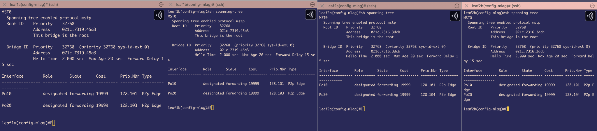 Figure 12
Port-channels10 & 20 that are connected to Hosts identified as P2P Edge ports
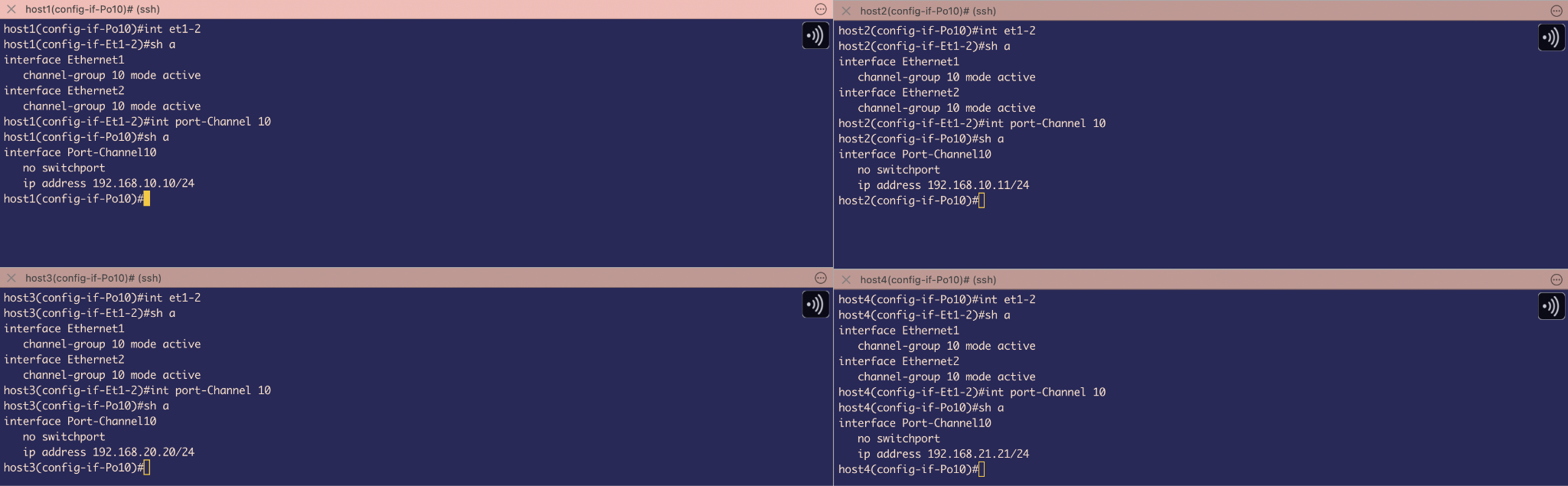 Figure 13
In the ideal case we would have Servers as Hosts and will be doing NIC teaming, However, since we are using cEOS , we will create port-channel10 according to topology on Host sides.
Also, we have created Port-channel 10 as L3 links using no switchport and assigned IP addresses according to the topology.
Port-channels are in LACP active mode to bundle Ethernet 1 and Ethernet 2 and now, from Hosts perspective , they think there is only 1 uplink leaf switch (1 Logical MLAG switch)
STP is DOWN but still we will not have any L2 Loops because of Port-channel load balancing and MLAG’s inherent loop-prevention mechanisms
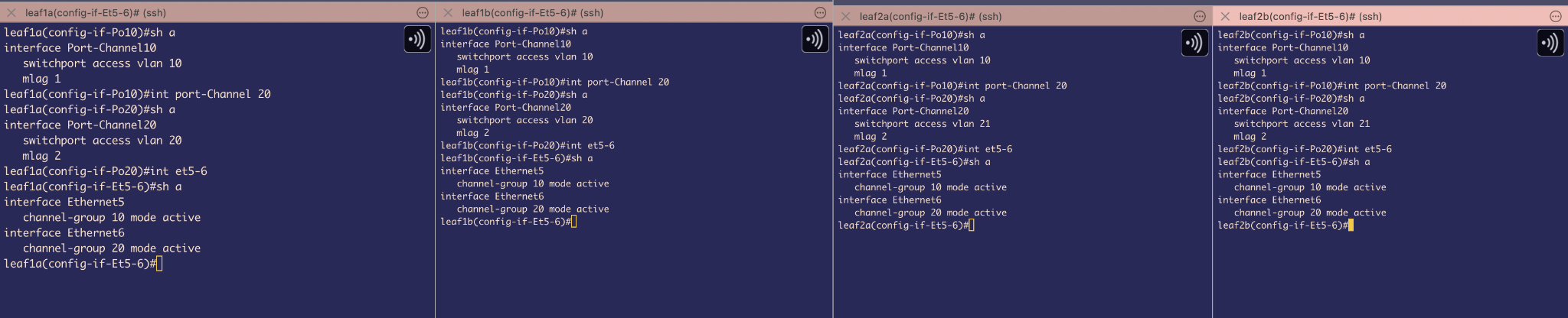 Figure 14
On MLAG Leafs1A&B and Leaf2A&B , we have bundled interface Ethernet5 of each to Port-channel 10 and Ethernet6 of each to port-channel 20
Used LACP in Active mode and because of this it sends 1 MLAG system-id for both switch downlink to hosts
These are Access switchports for VLAN 10 & 20
And all port-channels of both MLAG switches are glued together with mlag 1 and mlag 2 commands for port-channel 10 and port-channel 20 respectively.
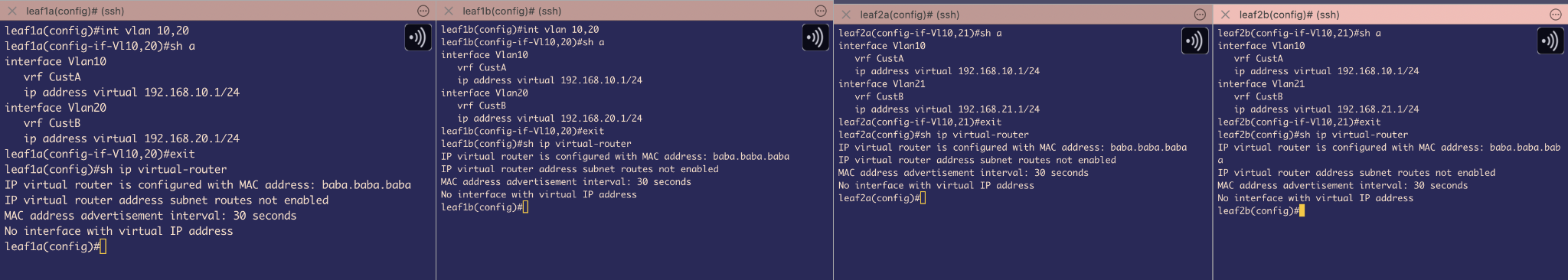 Figure 15
We also created L3 points using SVI 10 and SVI 20 to receive traffic coming from Hosts and keep them on those separate Broadcast domains of VLAN 10 & 20 respectively
According to topology we had to create VRFs –Host1&2 are on vrf CustA & Host3&4 on vrf CustB. This will give both tenants separate IP routing tables.
Also, we have assigned a virtual ip address, this is also called anycast gateway –its kind of a different flavour of VARP. Here, we do not require to assign individual IP addresses which saves IP addresses. Also, we have given a virtual MAC address too for ARP resolutions and this also prevents MAC flapping issues.
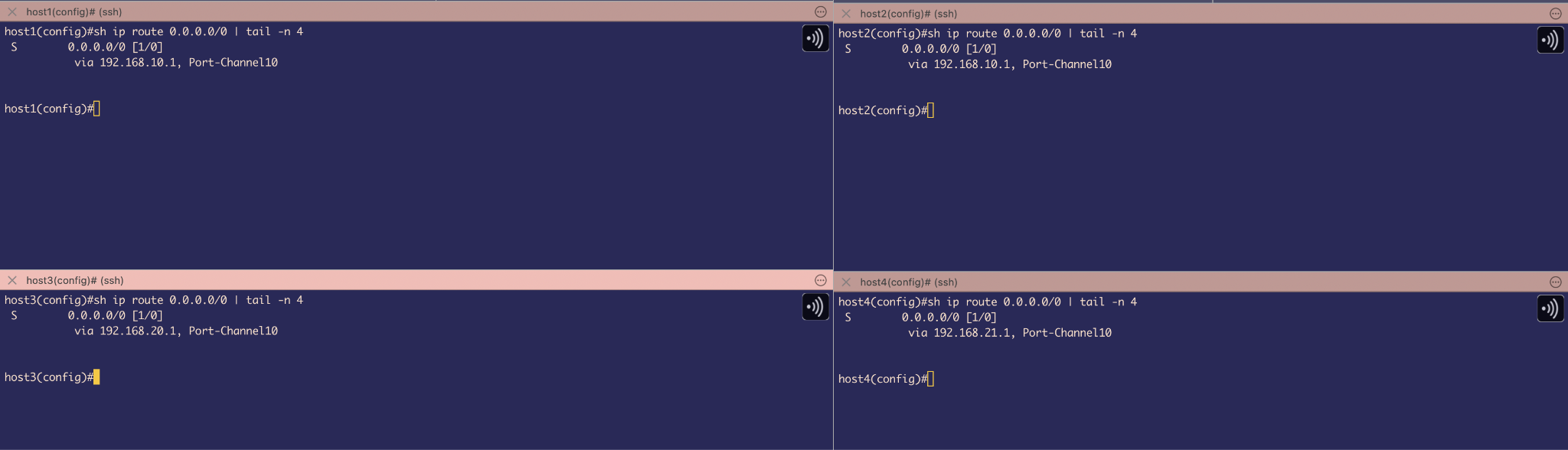 Figure 16
On host side, we have assigned Default gateway route to those virtual Ip addresses that we set on LEAF’s SVI
BGP configuration on Spine and Leafs
The first step is to establish BGP sessions between the point-to-point interfaces connecting the Spines and Leafs. The primary objective is to enable reachability to the Loopback0 and Loopback1 interfaces that will be configured on all Spine and Leaf devices.
To achieve this, BGP peering will be set up using the /31 point-to-point IP addresses assigned to the Spine-Leaf links.
Loopback0 will be used for EVPN BGP advertisements, including Type-2, Type-3, and Type-5 routes.
Loopback1 will be used as the source for VXLAN overlay tunnels.
This configuration ensures underlay connectivity for BGP sessions and provides the necessary loopback reachability to support EVPN and VXLAN overlays that we will be configuring later.
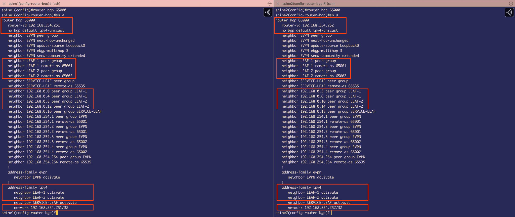 Figure 17
BGP configuration on Spines
At this stage, the focus is solely on configuring BGP to provide reachability to the loopback interfaces.
On the Spine switches, the router ID is set to the IP address of Loopback0. The default behavior of BGP to automatically advertise IPv4 unicast routes has been disabled. To compensate for this, IPv4 unicast route advertisements are manually activated for the peer-groups LEAF-1 and LEAF-2.
Since LEAF-1 and LEAF-2 belong to different autonomous systems, each peer-group is configured with the appropriate remote-as value. These peer-groups are then applied to the interfaces connected to the corresponding neighbor IP addresses.
Finally, the Loopback0 network is advertised into BGP using the network command, ensuring that reachability to the loopback addresses is established through these BGP sessions.
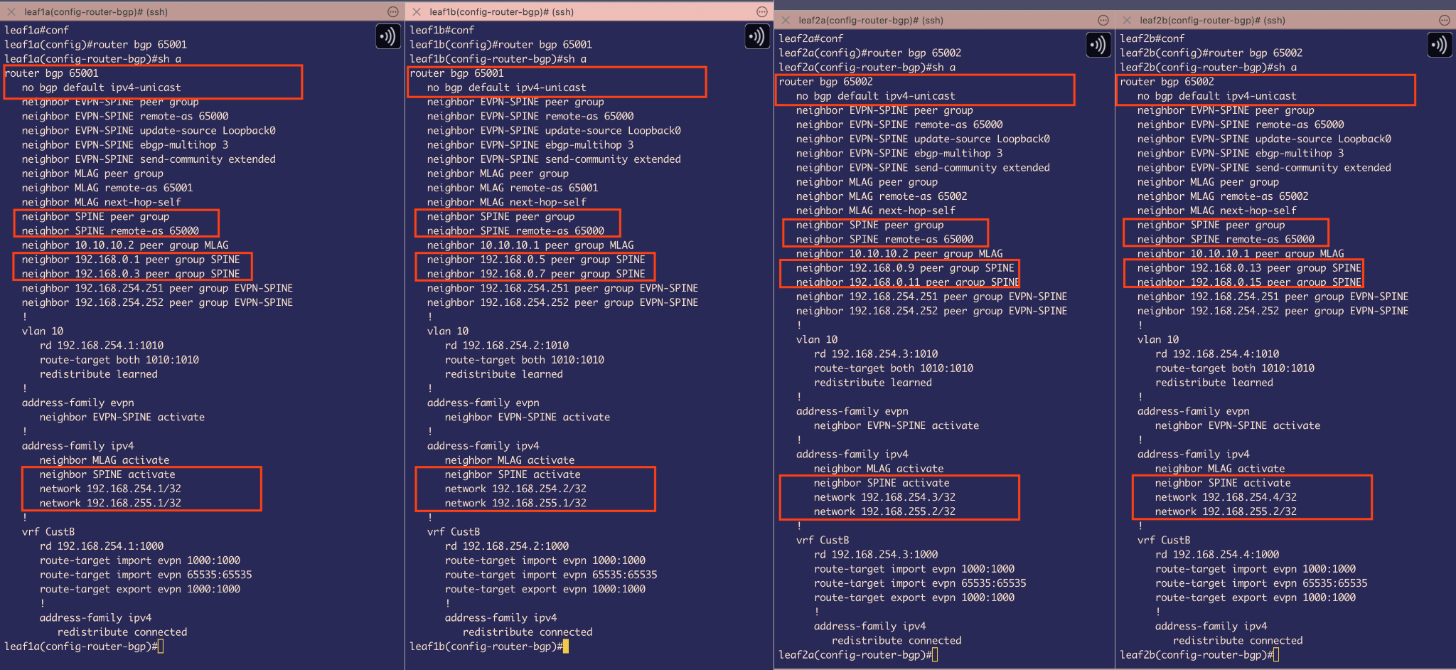 Figure 18
BGP configuration on Leafs
Similarly to the Spine configuration, BGP is configured on the Leaf switches using their respective AS numbers:
Leaf-1A and Leaf-1B – AS 65001
Leaf-2A and Leaf-2B – AS 65002
The default BGP behavior of automatically advertising IPv4 unicast routes is disabled. To compensate, IPv4 unicast route advertisements are manually activated under the address-family ipv4 for the peer-group SPINE.
Before this, the neighbor IP addresses of the Spine interfaces (forming the /31 point-to-point links) are added to the peer-group SPINE, which is configured with a remote-as of 65000.
Finally, both Loopback0 and Loopback1 addresses on each Leaf are advertised into BGP:
Loopback0 – Used for EVPN BGP route advertisements
Loopback1 – Used as the source for VXLAN tunnels (to be configured later)
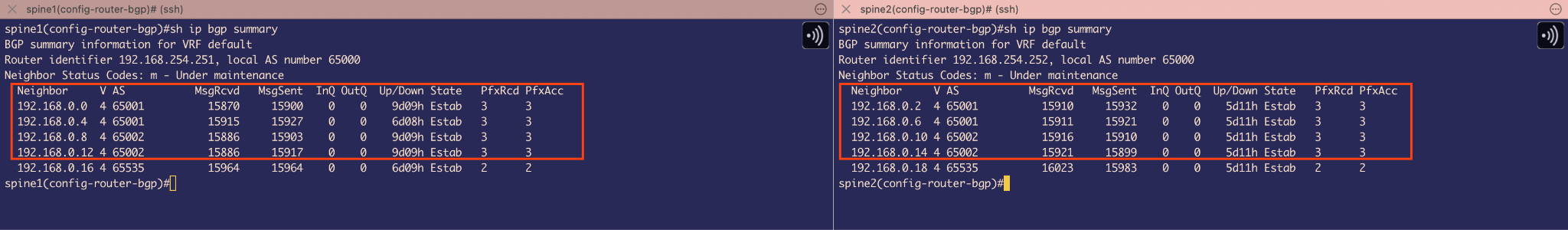 Figure 19
We can see on Spines that BGP sessions for individual interfaces are in Established State.
Backup Routes for Failover via MLAG Peer-Links on Leaf Switches
We must also account for a potential failover scenario where Ethernet1 & Ethernet2, the interfaces connecting the Leaf switches to the uplink Spines, goes down. In such cases, we want the Leaf switches to use the MLAG peer-link SVI 4094 to maintain the BGP sessions, ensuring continuous reachability to the Loopback interfaces.
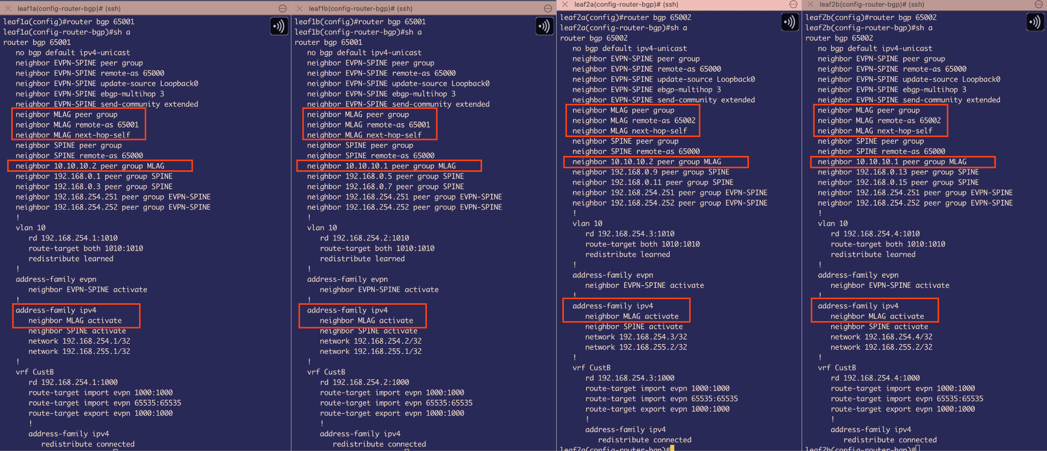 Figure 20
I have created an MLAG peer-group and assigned it a remote AS of 65001 for the Leaf 1 side and 65002 for the Leaf 2 side, as each MLAG pair belongs to its respective AS.
An important detail here is the use of the next-hop-self command. To understand why, imagine this scenario: Loopback4 routes advertised from Leaf 2 (AS 65002) are sent to the Spine (AS 65000). Since the Spine is in a different AS, eBGP changes the next-hop address to its own IP when advertising the Loopback4 route to Leaf 1 (AS 65001).
Now, suppose Leaf 1A’s Ethernet1 and Ethernet2 interfaces go down. Because we have an MLAG iBGP peering established between Leaf 1A and Leaf 1B, iBGP will advertise the Loopback4 route to Leaf 1A via Leaf 1B. However, iBGP does not automatically update the next-hop address to itself. As a result, Leaf 1A sees the Loopback4 route with a next-hop that points to the Spine neighbor of Leaf 1B — which Leaf 1A cannot reach directly. This causes Leaf 1A to lose reachability to Loopback4 and drop those advertised routes.
To avoid this, we use next-hop-self on the MLAG iBGP peer-group, forcing Leaf 1B to advertise itself as the next-hop for routes that are being advertised to Leaf 1A, ensuring proper loopback reachability even during failover.
And we also need to activate peer-group MLAG under the ipv4 address family so that unicast routes get advertised.
Overlay Network configuration
VXLAN & EVPN configuration
From our topology we need overlay network to support 2 things –
VXLAN Bridging for VLAN 10 as Host 1 and Host 2 are in same broadcast domain VLAN 10 and in same subnet
Symmetric EVPN Routing between Host 3 on VLAN 20 and Host 4 on VLAN 21
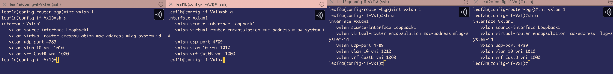 Figure 21
Interface VXLAN 1 configuration
First, I have configured Loopback1 to serve as the source IP address for the VTEPs.
There are two VTEPs in total:
Leaf 1A & Leaf 1B share the same VTEP Loopback1 IP: 192.168.255.1/32
Leaf 2A & Leaf 2B share the same VTEP Loopback1 IP: 192.168.255.2/32
Next, the VTEPs are configured to listen for the MLAG-assigned common system ID, ensuring synchronization between the MLAG peers.
The UDP port used for VXLAN encapsulation is set to the default 4789.
Following that, VLAN-to-VNI mapping is defined using the command vxlan vlan 10 vni 1010. This command serves two purposes: it facilitates both the encapsulation and decapsulation of VXLAN-encapsulated packets for VLAN 10.
To understand the next command, recall that Host 3 and Host 4 are in the VRF CustB and require symmetric routing, which means using a common Layer 3 VNI tunnel.
The command vxlan vrf CustB vni 1000 maps the IP VRF CustB to VNI 1000, enabling encapsulation and decapsulation of VXLAN packets within that VRF.
Because, if we think about the High-level view of the packet flow, for example, When Host3 on VLAN 20 pings Host4 on VLAN 21, the ICMP packet reaches VTEP1 where the receiving SVI 20 (configured in VRF CustB) performs a routing lookup in the VRF CustB table and discovers an EVPN Type-5 route to VLAN 21’s subnet via L3 VNI 1000 pointing to VTEP2. The packet is VXLAN encapsulated with L3 VNI 1000 and routed through the underlay to VTEP2, where the VXLAN header is stripped and the L3 VNI 1000 mapping places the packet into VRF CustB. VTEP2 then performs IP routing within VRF CustB to locate the destination subnet, performs ARP resolution if necessary, and forwards the packet to Host4 on VLAN 21.
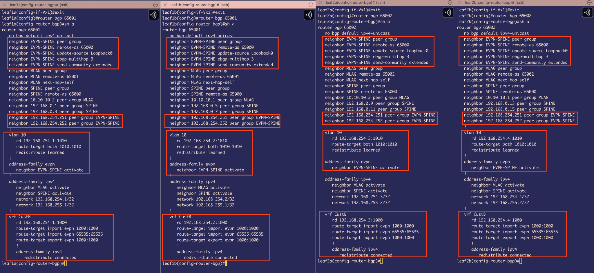 Figure 22
BGP EVPN configuration on Leafs
When considering the VLAN 10 bridging aspect of VXLAN, the Head-End Replication (HER) list must include both VTEP 1 and VTEP 2.
To achieve this, EVPN Type-3 route advertisements are used to distribute the replication list to all participating VTEPs. Additionally, EVPN Type-2 route advertisements are utilized to advertise the MAC addresses of the hosts along with the associated VTEP. This eliminates the need for flooding unknown unicast traffic by allowing each VTEP to learn exactly which MAC address is reachable through which VTEP.
Under BGP configuration I created a peer-group EVPN-SPINE, and this BGP’s TCP session will be established between Loopback1 to Loopback1 between SPINE and LEAFS
Next, I have used ebgp-multihop 3 that configures the switch to accept and attempt BGP EVPN connections to the external peers residing on networks not directly connected to the switch. Well, this is important if we think about the Failover case, where eth1 and eth2 goes down for a Leaf , but we still want EVPN BGP sessions to be UP even though that disconnected Leaf wont be directly connected to spine but indirectly through out MLAG peer-link BGP session as underlay.
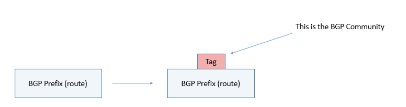 Figure 23
Next command, neighbor EVPN-SPINE send-community extended, tells EVPN BGP sessions to also include a tag/metadata with their route advertisements. These tags will be a transitive BGP attribute, meaning that if they exist they should be propagated to all BGP neighbors. We are using Extended community because it is a 64 bit community as we need it to send Route-targets that will be used for importing and exporting of routes in the EVPN domain.
Then we have assigned the neighboring IPs of Spine 1 and Spine 2 with this peer-group
Next, we have used vlan 10 to create a VLAN 10 MAC-VRF which the switch is going to use to store all the MAC addresses that belong to VLAN 10 domain.
The Route Distinguisher uses the format Loopback0:VNI to create globally unique route identifiers within the EVPN control plane. This prevents BGP from treating identical IP prefixes as duplicates when they exist in different VRFs or VLANs. For example, if VLAN 10 and VLAN 20 both contain a host with IP address 192.168.10.10/24, standard BGP would consider these identical prefixes and potentially drop one during route selection. However, with RDs (e.g., 10.1.1.1:10010 for VLAN 10 and 10.1.1.1:10020 for VLAN 20), BGP treats each route as globally unique, ensuring proper route advertisement and preventing unintended route suppression across the EVPN fabric.
Next we have used route target in the following format: route-target both VNI:VNI
This command configures both import and export route targets with the same VNI value, enabling the VRF to both advertise and accept EVPN Type-2 (MAC/IP) and Type-3 (IMET - Inclusive Multicast Ethernet Tag) route advertisements.. This allows proper L2 forwarding and BUM (Broadcast, Unknown unicast, Multicast) traffic handling across the VXLAN fabric for hosts within the same VLAN/VNI.
The redistribute learned command instructs the VTEP to advertise all locally learned MAC addresses into the EVPN domain using the configured route-targets and route-distinguishers. This enables distributed MAC learning across the fabric, where each VTEP shares its local MAC address table with remote VTEPs through EVPN Type-2 route advertisements. When a host sends traffic, the local VTEP learns the MAC address using Data plane learning and immediately advertises it to other VTEPs in the same broadcast domain and for those other VTEPs in network this remote MAC is learnt via control plane learning, eliminating the need for traditional flooding-based MAC learning and enabling optimal traffic forwarding across the VXLAN overlay.
Now, for symmetric routing to take place between VLAN 20 and VLAN 21 for host 3 and host 4 via L3 VNI 1000. We have to configure BGP to use VRF CustB.
Under VRF CustB, we have done quite similar things as before, given it a route-distinguisher for routes to be unique
Also configured a route-target for import and export of routes –At this point , we only care about route-target import/export 1000:1000
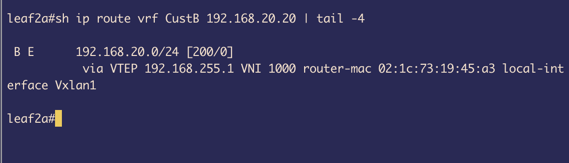 Figure 24
Under the IPv4 address family, the redistribute connected command advertises directly connected subnets as EVPN Type-5 routes to remote VTEPs. This enables inter-subnet routing across the VXLAN fabric by sharing IP prefix reachability information through the EVPN control plane. When LEAF1 advertises its connected VLAN subnets with route-target 1000:1000, LEAF2 imports these Type-5 routes (due to matching import route-targets) and installs them in its VRF CustB routing table.
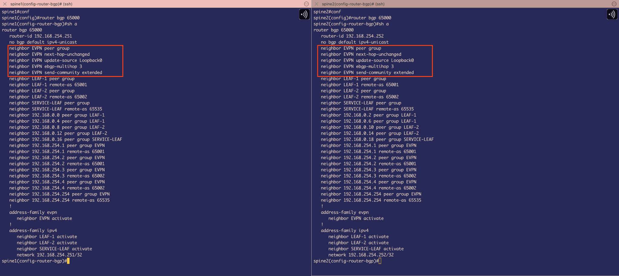 Figure 25
BGP EVPN configuration on Spine
The EVPN base configuration is quite similar to Leaf. We need to remember that Spines dont care about VXLAN and their job is just to route the traffic to its destination, so we dont have any MAC VRF or IP VRF setup here.
The neighbor EVPN next-hop-unchanged command is configured on spine switches to preserve the original VTEP loopback addresses in EVPN route advertisements. By default, eBGP changes the next-hop to the advertising router’s interface address when propagating routes. However, in EVPN fabrics, we need the next-hop to remain as the originating VTEP’s loopback address (VTEP source) to ensure proper VXLAN tunnel establishment. Without this command, when VTEP1 advertises EVPN routes through the spine to VTEP2, the spine would change the next-hop from VTEP1’s loopback to the spine’s own interface, breaking VXLAN encapsulation since tunnels must terminate at the actual VTEP endpoints, not the intermediate spine switches(as Spines are not doing any VXLAN encapsulation but only routing the traffic to destination).
Host Reachability Test
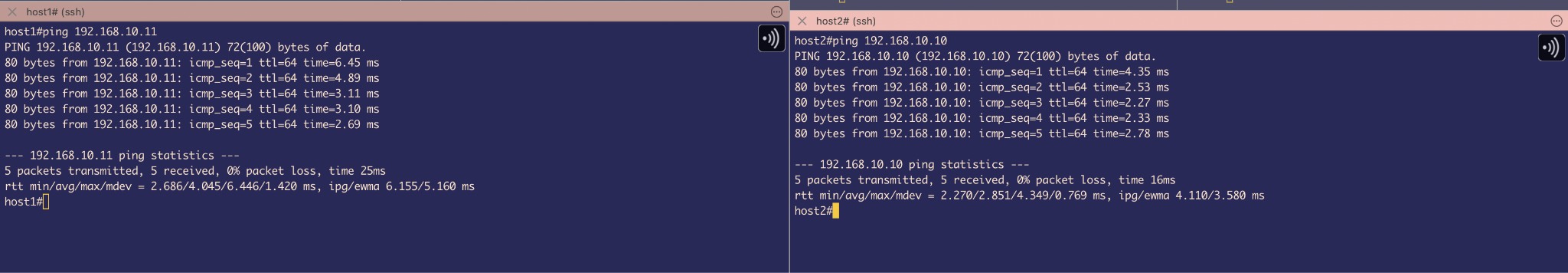 Figure 26
We have used a simple ping command to test out configuration. Host 1 (192.168.10.10 ) on VLAN 10 pings Host 2 (192.168.10.11) on same VLAN 10. Packet goes through VXLAN encapsulation and bridging happens. The TTL remains 64 indicating a successful VXLAN bridging.
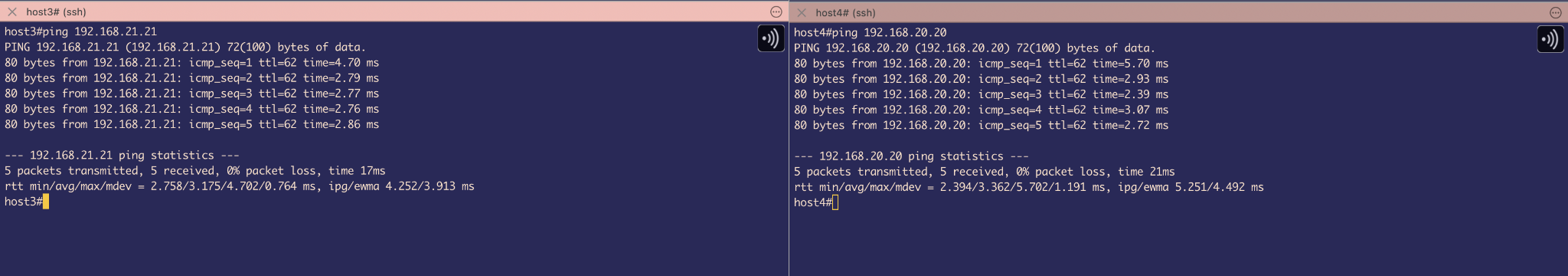 Figure 27
Testing connectivity between Host3 (192.168.20.20) on VLAN 20 and Host4 (192.168.21.21) on VLAN 21 demonstrates symmetric IRB (Integrated Routing and Bridging) operation. The successful ping with TTL 62 confirms that packets are being routed at both VTEPs. The packet flow involves routing at the ingress VTEP (VLAN-to-L3VNI), VXLAN encapsulation through tunnel VNI 1000 across the fabric, decapsulation at the egress VTEP, and final routing from L3VNI to the destination VLAN. The TTL decrement of 2 (from typical 64 to 62) indicates two routing hops - one at each VTEP - confirming the symmetric model where both ingress and egress VTEPs perform L3 forwarding functions.
External connectivity configuration
Now, we will be configuring the ServiceLeaf and FW to simulate external connectivity and make Devices on VRF CustB reachable to Internet
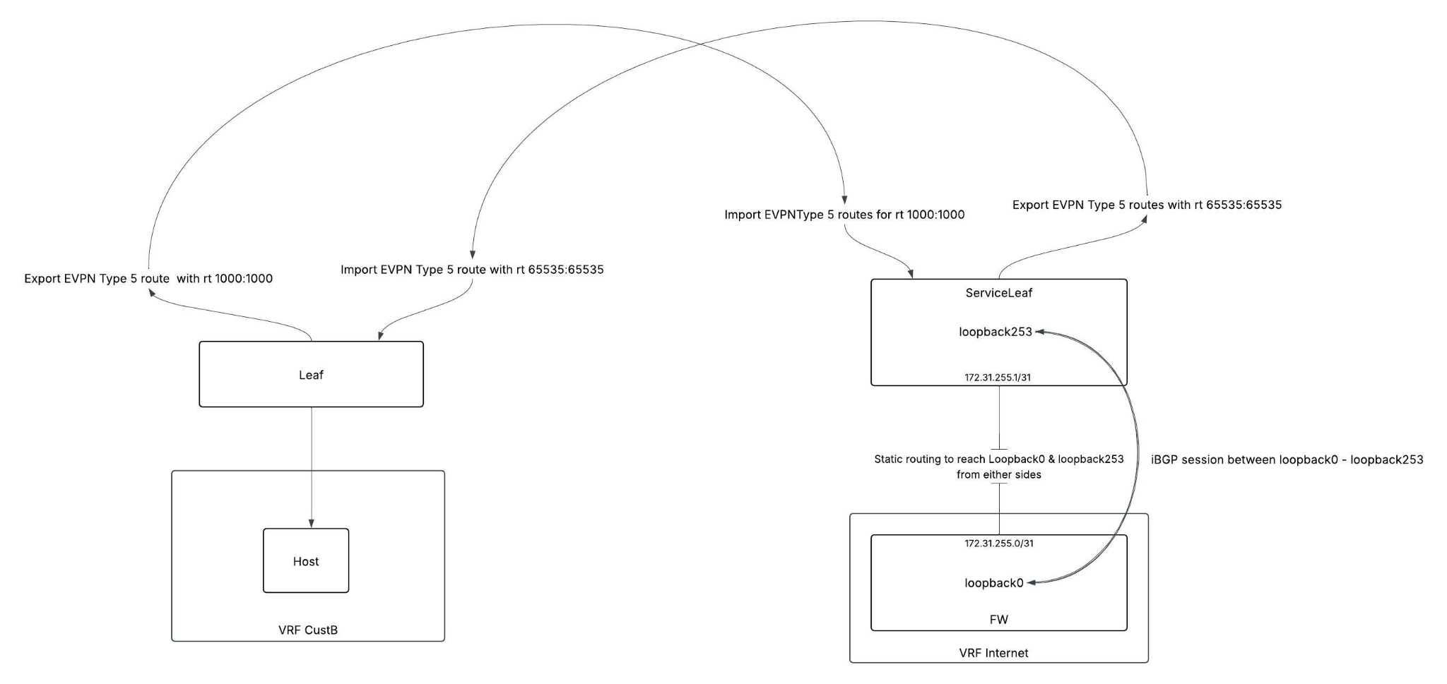 Figure 28
So the main idea is to have iBGP sessions established between loopback to loopback as iBGP sessions are established between loopback interfaces as a best practice for enhanced reliability, ensuring BGP connectivity remains stable even when individual physical links fail, leveraging the multiple redundant paths typically present in production networks.(But here since we only have 1 physical link for this lab, if physical connectivity goes down then the ibgp session also terminates).
This iBGP session will be used by FW to advertise loopback121 to loopback129’s reachability info to serviceleaf and then service leaf can attract traffic from vrf CustB that wants to reach Internet (simulated external connectivity with those loopbacks) and respond to it.
We will also need to export and import some Type 5 routes in our EVPN domain , as we will be doing Asymmetric Routing using L3 VNI. First, I am going to advertise IP-prefixes of those Loopback121 to loopback129 from Service leaf using route-target 65535:65535 then on Leaf 1 and Leaf 2 and will be importing those routes under VRF CustB.
And the exported routes from Leaf with route-target of 1000:1000 will be imported on ServiceLeaf because we need to think about the return traffic too and for that I need type-5 routes coming from Leaf and fill those on Service Leaf’s Internet VRF’s routing table.
Configuration on FW and Service Leaf:
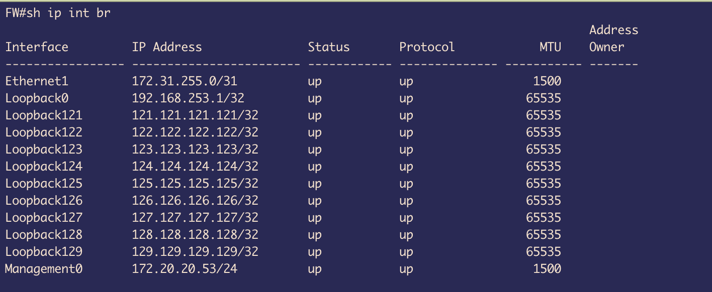 Figure 29
On FW , we created loopbacks 121 to loopback 129
Loopback0 will be used for iBGP session establishment
Ethernet 1 will be used for static routing providing the underlay for iBGP session.
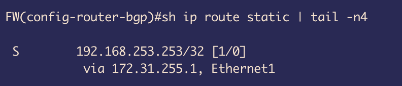 Figure 30
We created a static route to create reachability to Loopback0(192.168.253.253/32) of ServiceLeaf through the physical interface ethernet 1
This will be used to establish iBGP session between Loopback0 of FW to Loopback 253 of Service Leaf
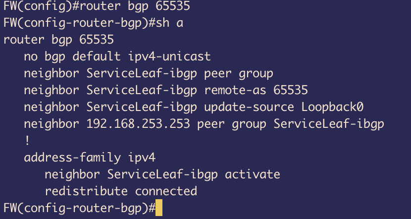 Figure 31
In the BGP configuration, we have disabled the default behaviour of getting IPv4 family being advertised and manually activated it instead
Created a peer-group ServiceLeaf-ibgp with remote-as 65535
This BGP’s TCP session will be established between Loopback0 to Loopback253 (service-Leafs) and because of that we have updated the source to Loopback0 on FW
And under ipv4 family, we have used redistribute connected to advertise all the connected routes which includes Loopback121 to Loopback 129
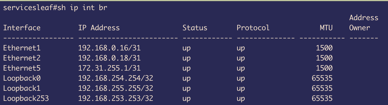 Figure 32
On Service Leaf, we got Ethernet1 and Ethernet 2 that are connected to Spine 1 and Spine 2 respectively for BGP underlay connectivity and EVPN sessions
Loopback0 is used for EVPN BGP session establishment
Loopback1 is used for VXLAN tunnels
Loopback253 is used for iBGP peering with FW
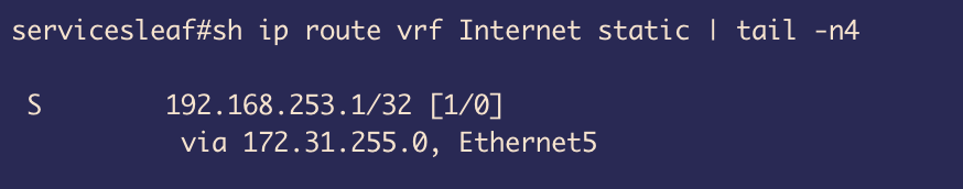 Figure 33
Ethernet5 is used for static routing to provide reachability to FW via VRF Internet
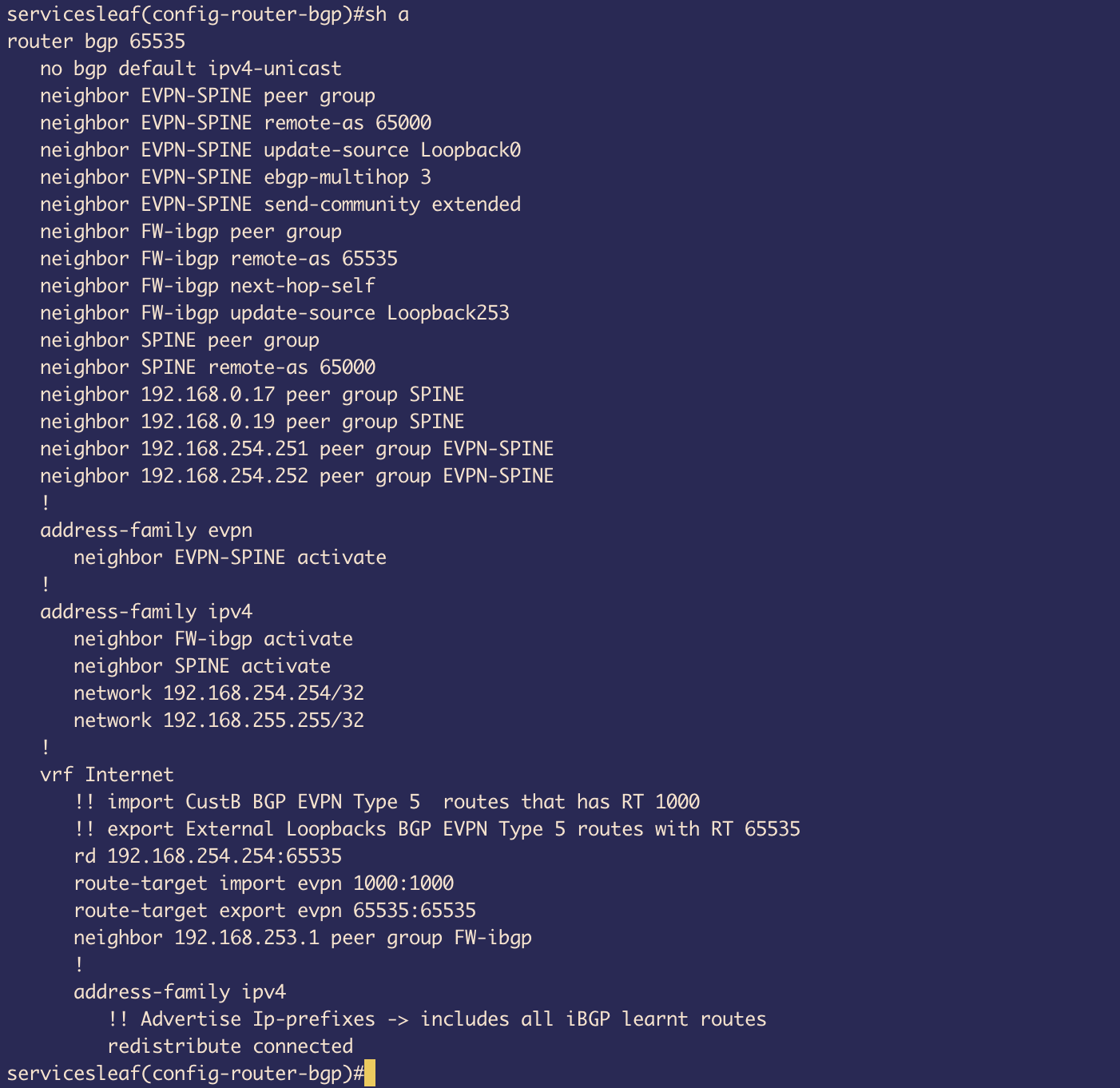 Figure 34
The Base configuration for BGP and EVPN sessions with Spines are quite similar to previous Leafs
One thing to note is that, we have created Internet VRF and under that used neighbor 192.168.253.1 peer group FW-iBGP. This is because interface Loopback253 is placed under vrf Internet so BGP cant see any Loopback253 on default VRF and we need to create this neighborship under vrf Internet
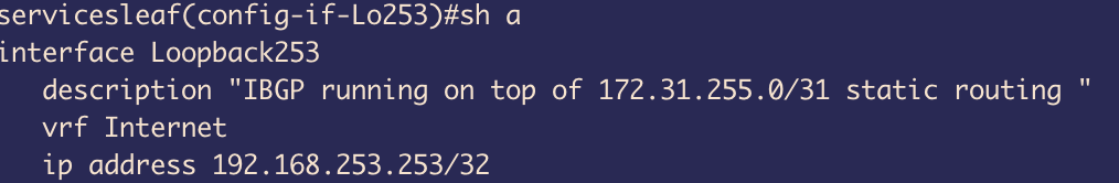 Figure 35
Loopback253 is under VRF Internet
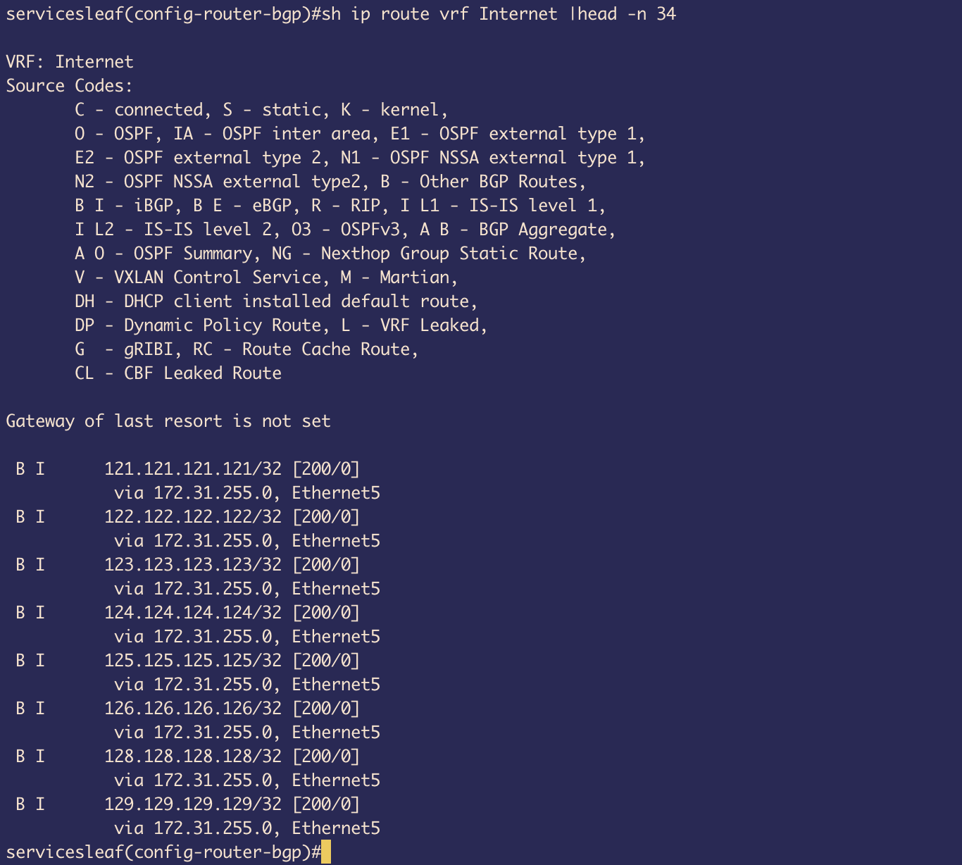 Figure 36
The peer-group FW-ibgp is used for establishing iBGP session and because of that we can see in the routing table under VRF Internet that we have all the routes to loopback121-129
Next, in the configuration we have used route-target import 1000:1000 because of this we get the route for return traffic back to CustB as the Type 5 EVPN routes from Leaf1&2 side are being advertised using rt 1000:1000
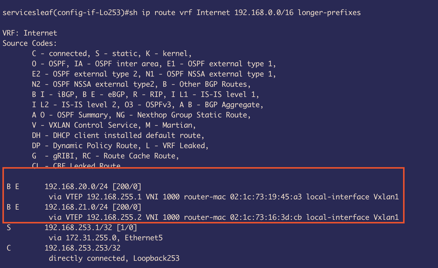 Figure 37
This return traffic will take L3 VNI 1000 as shown in the routing table.
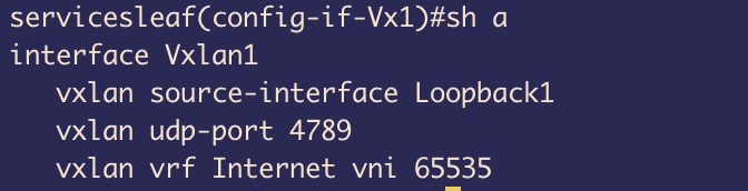 Figure 38
Under VXLAN 1 interface we have configured Loopback 1 to be used to establish the UDP connection
And with vxlan vrf Internet vni 65535 , we have glued the VRF Internet to VNI 65535 L3 tunnel.
This tunnel will be used for decapsulation of VXLAN packets as the traffic that wants to reach the internet will be coming with VNI 65535 as we have used this for Type 5 route advertisements.
And on receiving VXLAN encapsulated packets switch will check the Mapping and place the packet on Internet VRF
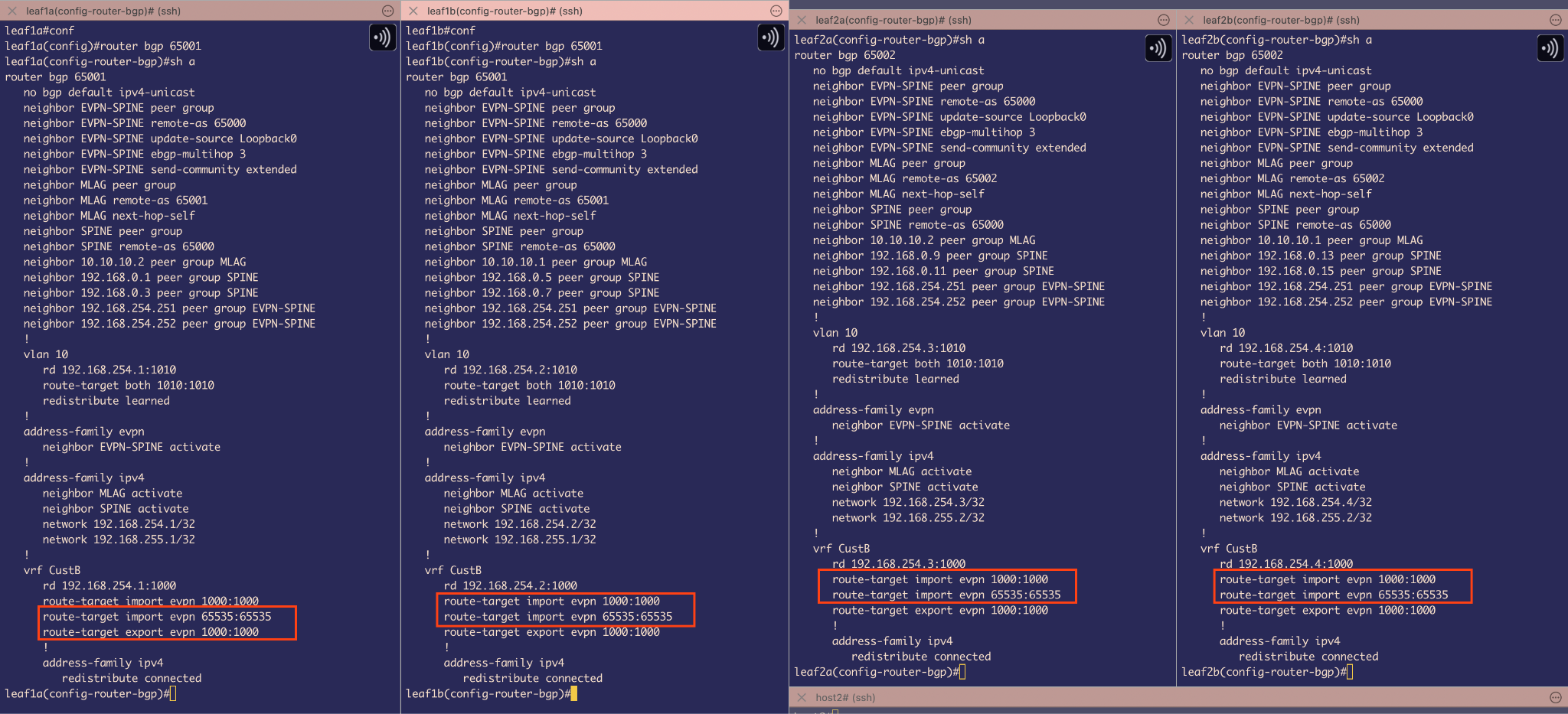 Figure 39
One last thing to do is on Leaf1 and Leaf 2 side, we need to write import statements with route-targets 65535
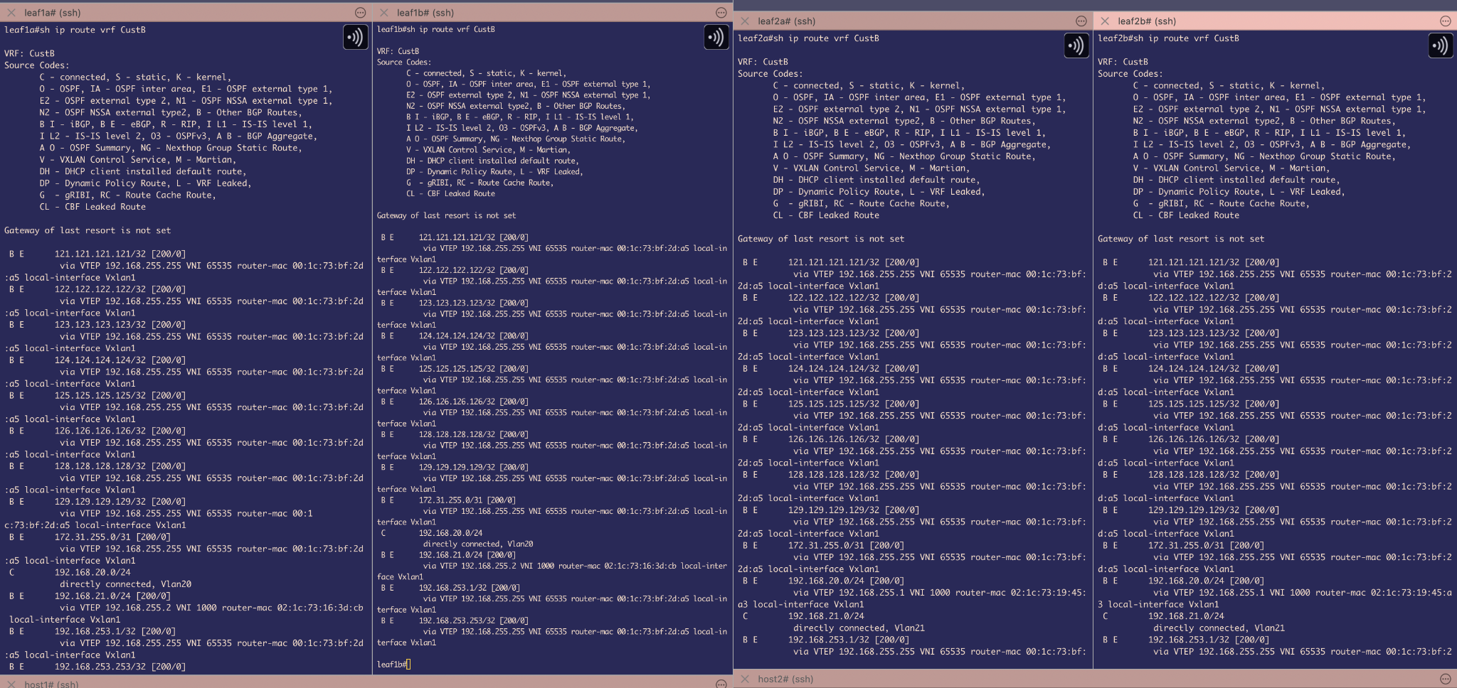 Figure 40
And because of the above import statement, in the routing table of VRF CustB we are able to see routes to reach those external destinations.
Reachability Test
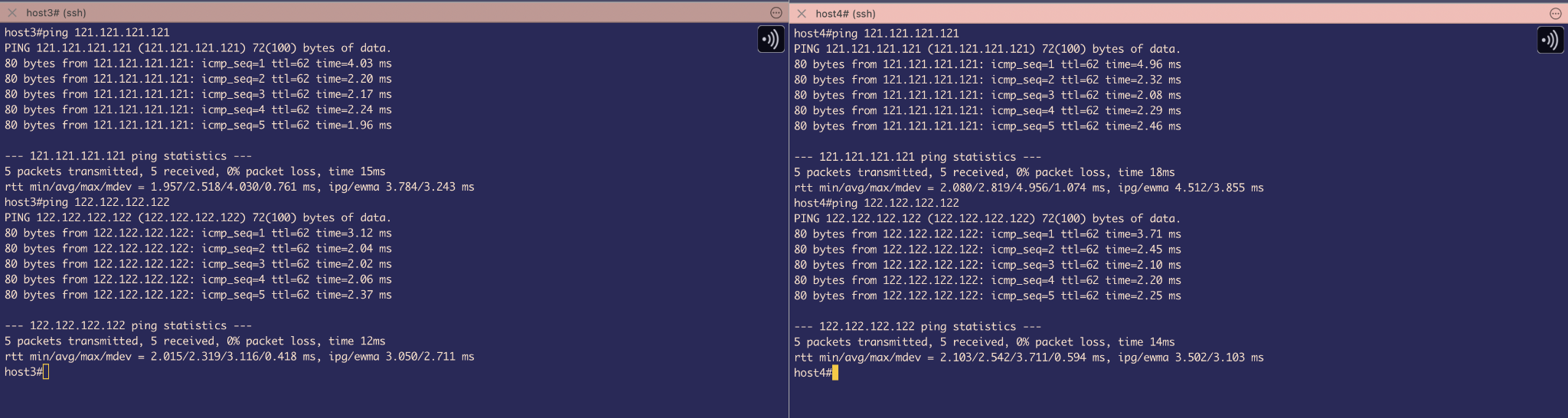 Figure 41
With a simple Ping test we can check the reachability of Hosts to External destinations. And TTL is 62 which is expected as we are using L3 VNI. However, for sending its using VNI 65535 and for receiving its using VNI 1000. We can verify this theory using TCPDUMP output
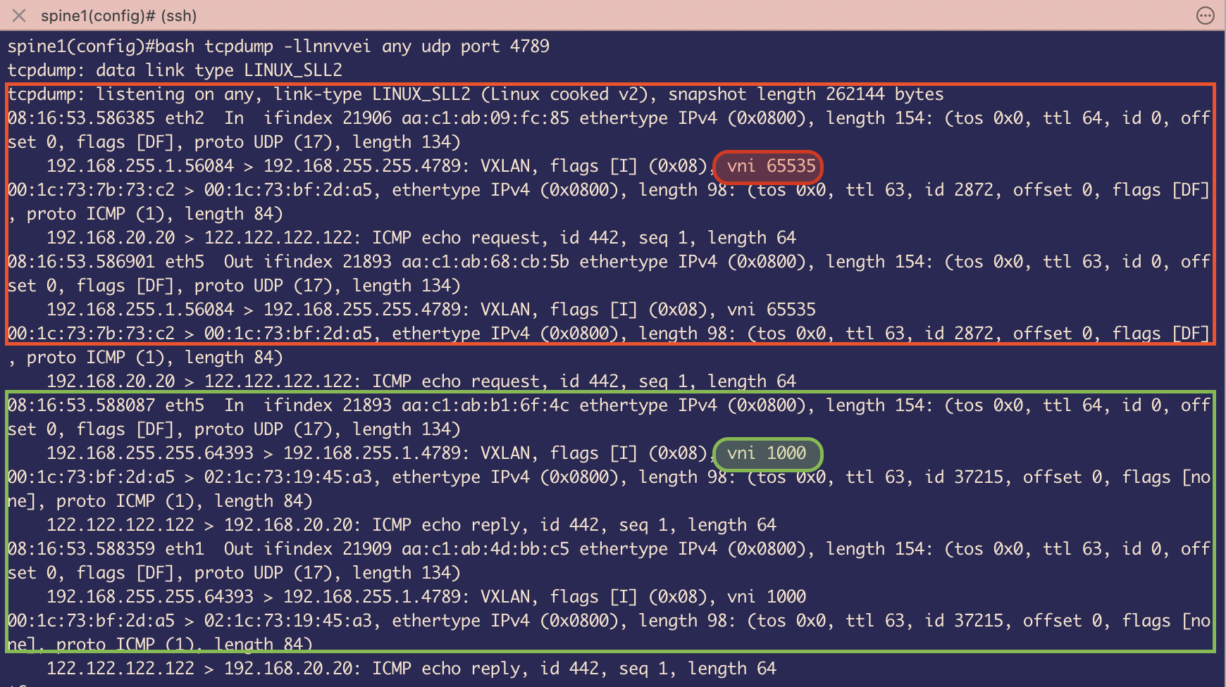 Figure 42
Here, I have captured ICMP request originating from host 3 and being delivered back to Host 3
ICMP request is going via VXLAN encapsulated packet using L3 VNI 65535
ICMP replies is coming via VXLAN encapsulated packet using L3 VNI 1000 as expected.
Note: The image path format /images/fp_imageX.png is critical. The leading / tells GitHub Pages to look from the root of your site, ensuring images load correctly.