
Leaf-Spine with MLAG (inter-vlan routing)
Published:
Objective
Create a standard L2 leaf/spine network in Containerlab Studio with:
- 2 spines
- 1x2 compute leafs
- 1x2 service leafs
- Leaf pairs in MLAG
- Configure several VLANs
- Use L2 trunking and MLAG port-channels
- Perform inter-VLAN routing on spines
- Simulate “external” connectivity on service leafs
- Enable routing to an “external” IP
Virtual Lab
We used ContainerLab, hosted internally by Arista, as the virtual lab environment. ContainerLab is a network emulation tool that leverages Docker to deploy container-based network topologies and supports multi-vendor device simulation.
Arista’s internal team built a custom interactive front-end GUI for managing ContainerLab, allowing us to:
- Drag and drop nodes
- Assign Arista cEOS /images for switches
- Use Linux containers for hosts
This front-end automatically generated the .yaml topology files used by Docker to instantiate the environment.
We also explored how Docker differs from virtual machines — particularly how Docker containers share the host’s kernel, allowing for lightweight and efficient deployment.
Topology Overview
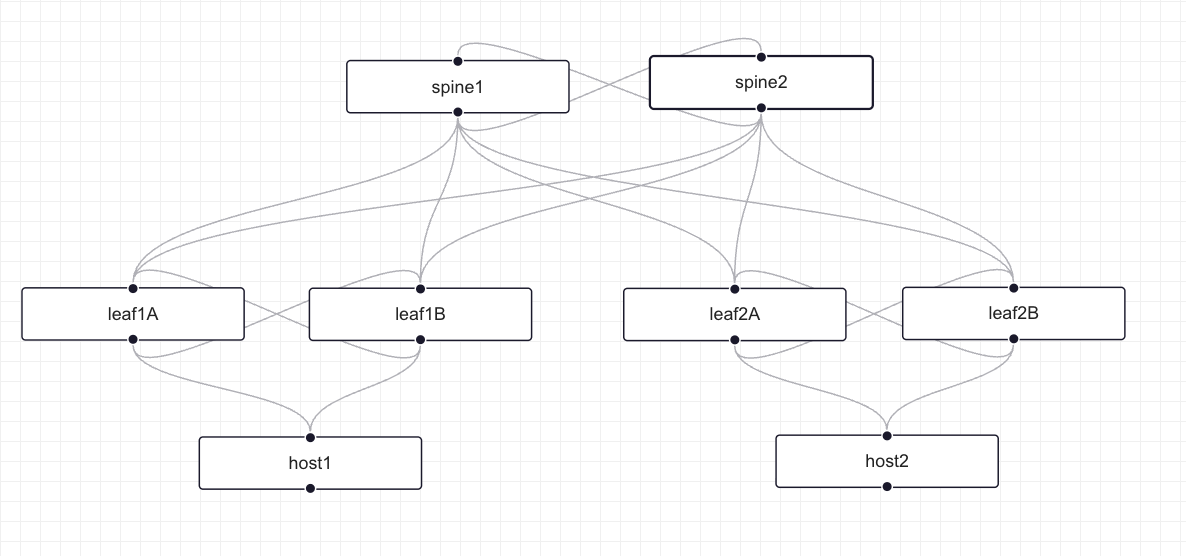 Figure 1: Basic L2 Leaf-Spine Network Topology created using ContainerLab Studio GUI
The topology consists of:
- 2 Spine switches (spine1, spine2)
- 4 Leaf switches arranged in 2 MLAG pairs:
- Compute Leaf Pair: leaf1A and leaf1B
- Service Leaf Pair: leaf2A and leaf2B
- 2 Hosts (host1, host2)
Network Topology Design and Configuration
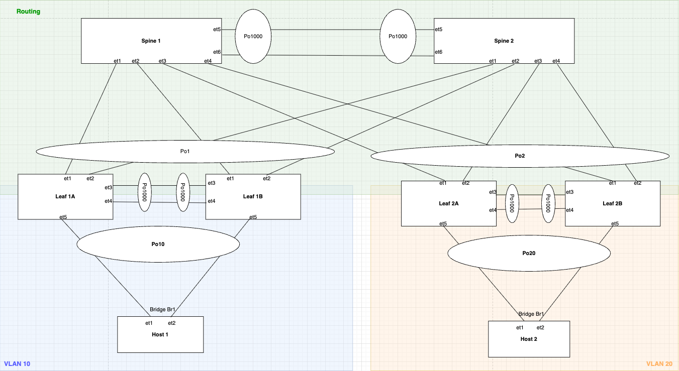 Figure 2: Detailed Leaf-Spine Topology with MLAG, VLANs, and Port-channels showing the routing layer
This is a Leaf-Spine topology with MLAGs featuring:
- VLAN 10 on Compute Leaf pair (leaf1A/1B) → Host1
- VLAN 20 on Service Leaf pair (leaf2A/2B) → Host2
- VLAN 100 for WAN/External traffic
- VLAN 4094 for MLAG peer communication
- Port-channels (Po1, Po2, Po10, Po20, Po1000) for link aggregation
- MLAG domain IDs for logical switch pairing
1. Spine Switches in MLAG and VARP & IP Routing Configuration
Spine switches handle the routing functions in this topology and are configured with both MLAG and VARP to provide Layer 2 and Layer 3 redundancy respectively.
MLAG (Multi-Chassis Link Aggregation) is Arista’s implementation of a technology that allows two switches to appear as a single logical switch for L2 link aggregation.
Steps to Configure MLAG:
Step 1: Check if Control-Plane ACL allows MLAG traffic
The default control plane ACL protects the CPU as ASIC punts all the CP packets to it. These specific lines permit TCP/UDP traffic (MLAG uses TCP/UDP for peer communication) coming from any source IP with destination port “mlag” (4432) and TTL value of 255 (directly from peer, as packet’s default TTL is 255).
 Figure 3: Control Plane ACL configuration on Spine1 showing MLAG traffic permission
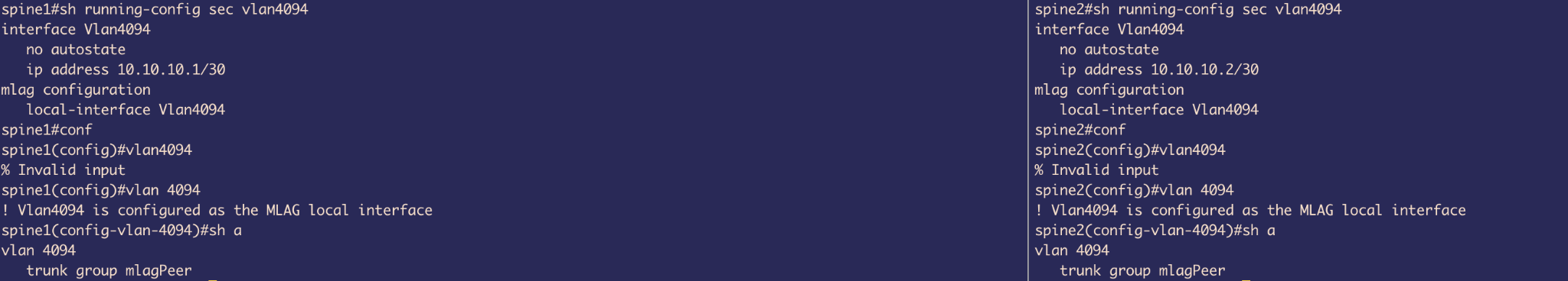 Figure 4: Control Plane ACL configuration on Spine2
Step 2: Create Peer links and VLAN 4094
Create VLAN 4094 (Arista default VLAN used by MLAG), over which peer switches will have peer-to-peer communication. We use 2 interfaces in Port-channel for L2 redundancy.
 Figure 5: SVI VLAN 4094 configuration on Spine1 for MLAG peer communication
Configuration highlights:
- Created SVI vlan4094 and assigned it an IP because MLAG communication happens using TCP/UDP
- Used
no autostateto lock the interface in UP state - Created a trunk group called
mlagPeeras an elegant way to exclude VLAN 4094 from other MLAG member ports - If any other interface is trunk and allows VLAN 4094, it still does not send traffic because we still need to add that group to the interface (a safety measure)
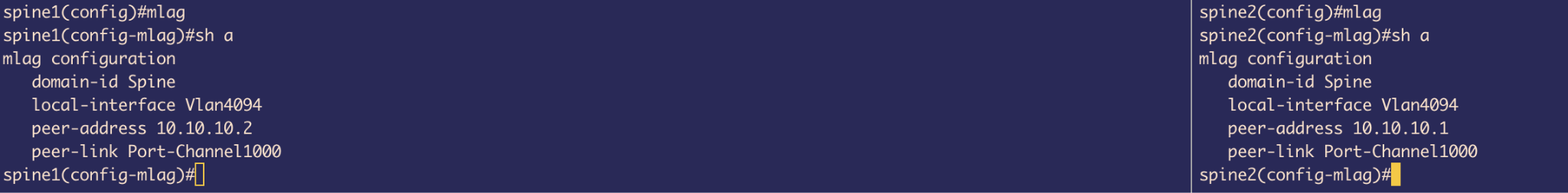 Figure 6: Port-channel 1000 configuration on Spine1 with mlagPeer trunk group
- Created Port-channel 1000 and bundled 2 interfaces (et3 and et4)
- Set mode to trunk and included mlagPeer group
- Disabled spanning tree from running on vlan4094
Even though Arista switches use MSTP flavor of STP by default (which is not per VLAN basis), we want to be extra careful and don’t want MLAG VLAN from ever participating in STP.
Step 3: Configure the MLAG itself
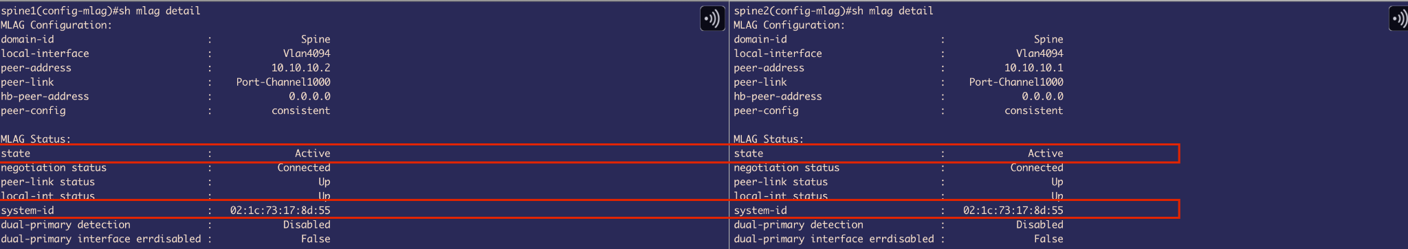 Figure 7: MLAG domain configuration on Spine1
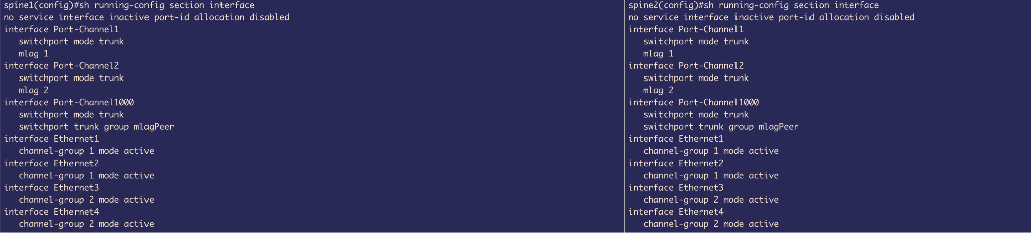 Figure 8: MLAG domain configuration on Spine2
Configuration includes:
- Domain-ID
- Local-interface
- Peer-address
- Peer-links
Step 4: MLAG Status Verification
Now MLAG is Active and both switches have the same System-ID which is used by LACP to advertise the same System-ID from both sides. This tricks the downlink leaf switch to believe that there is only 1 uplink switch (logical 1 switch using MLAG).
 Figure 9: MLAG status on Spine1 showing Active state and consistent System-ID
 Figure 10: MLAG status on Spine2 showing Active state and matching System-ID
Step 5: Configure MLAG member ports
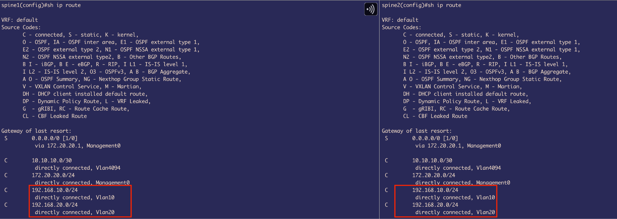 Figure 11: MLAG member port configuration on Spine1
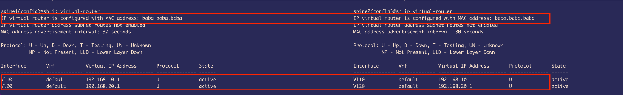 Figure 12: MLAG member port configuration on Spine2
- Included et1 & et2 into Port-channel 1 and et3 & et4 into Port-channel 2
- Both switches are glued together using
mlag 1andmlag 2commands used on port-channels respectively
VARP Configuration for Layer 3 Redundancy
VARP (Virtual ARP) - Arista specific First Hop Redundancy Protocol (FHRP) enables multiple switches to share a virtual IP and virtual MAC address as the default gateway for connected VLANs.
VARP allows Active-Active forwarding - both uplink switches are able to perform routing, unlike VRRP (IEEE standard) which allows Active-standby forwarding, where it elects a VRRP Master peer switch that performs routing and the other peer switch is VRRP backup that forwards routing traffic to Master peer that actually routes it.
Before configuring VARP, we first need to:
- Enable IP routing
- Set up SVIs (Switched Virtual Interfaces)
VLAN Configuration:
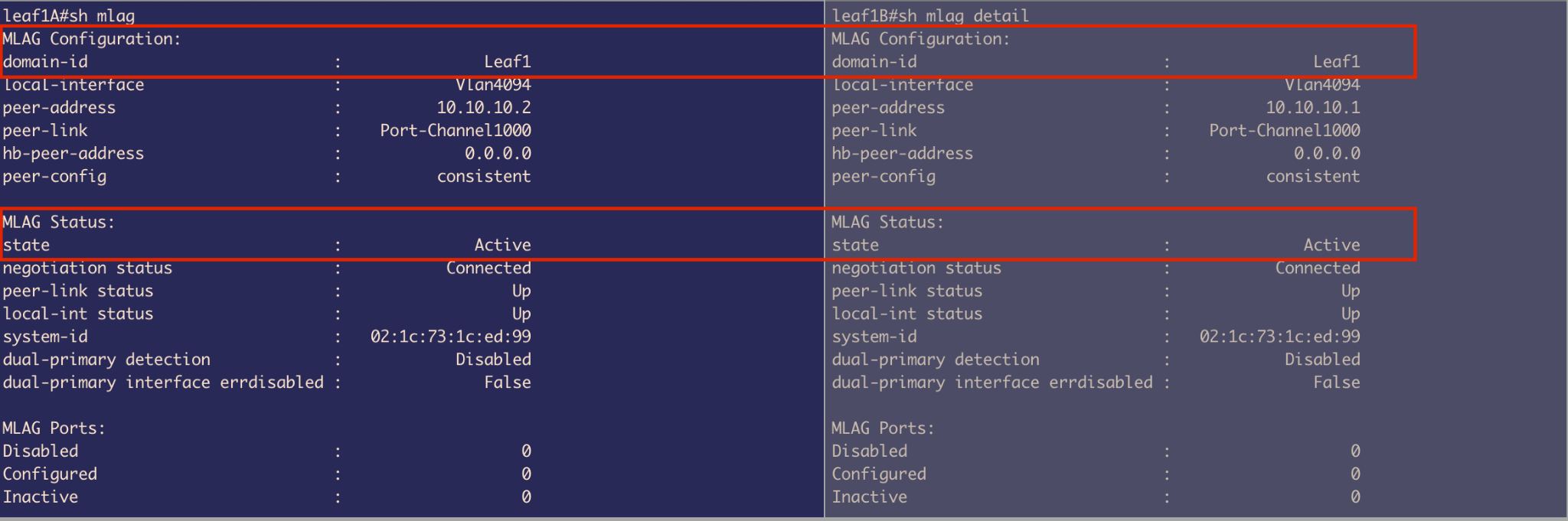 Figure 13: VLAN configuration on Spine1
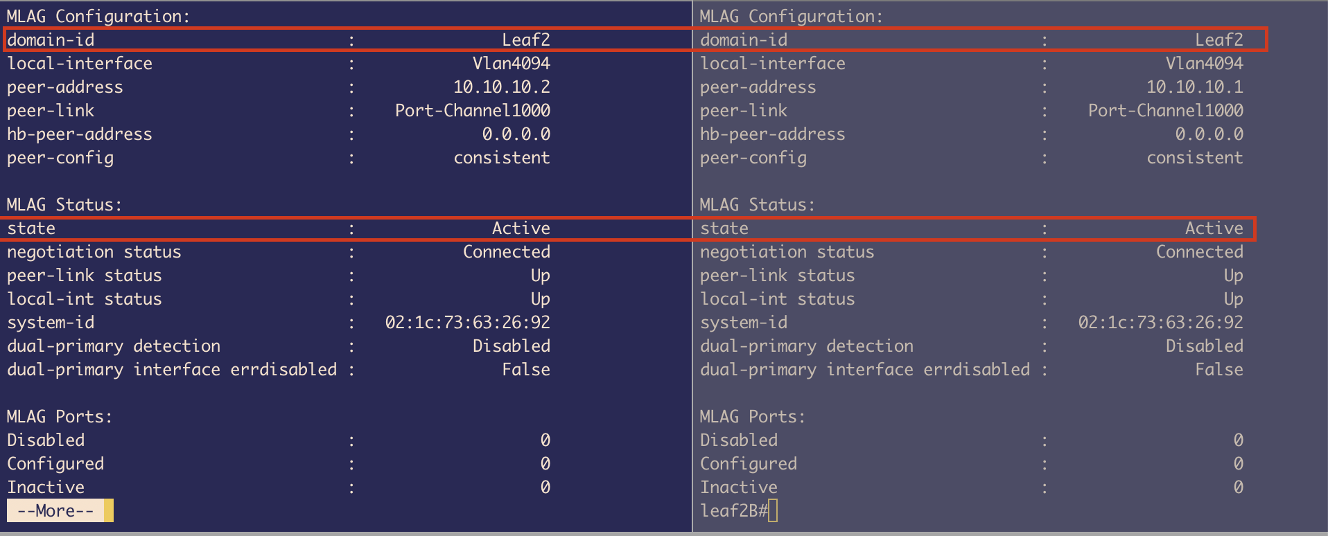 Figure 14: VLAN configuration on Spine2
- Created VLAN 10 and VLAN 20
- Created 2 SVIs (L3 links) with IP addresses:
- VLAN 10: 192.168.10.2/24 & 192.168.10.3/24
- VLAN 20: 192.168.20.2/24 & 192.168.20.3/24
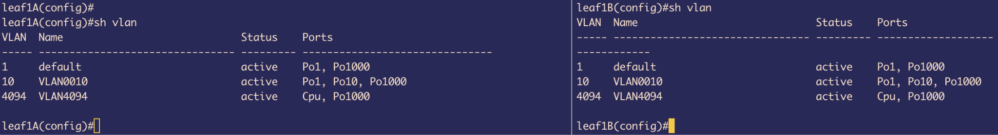 Figure 15: SVI VLAN 10 configuration on Spine1
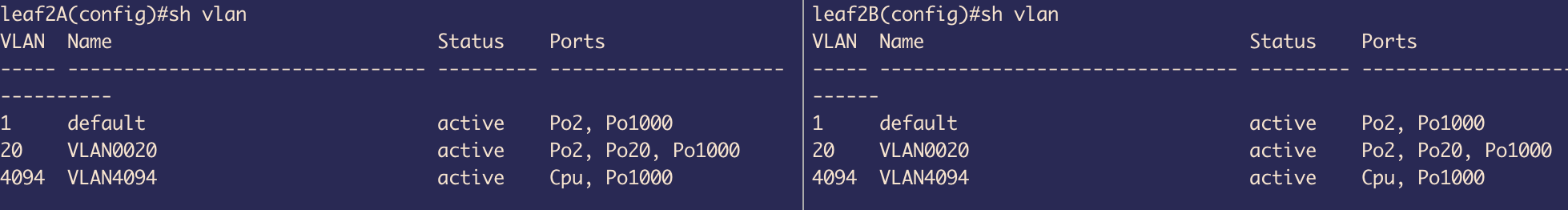 Figure 16: SVI VLAN 10 configuration on Spine2
The moment we created SVIs, we got 2 Connected routes defined for those 2 different subnets in our routing table.
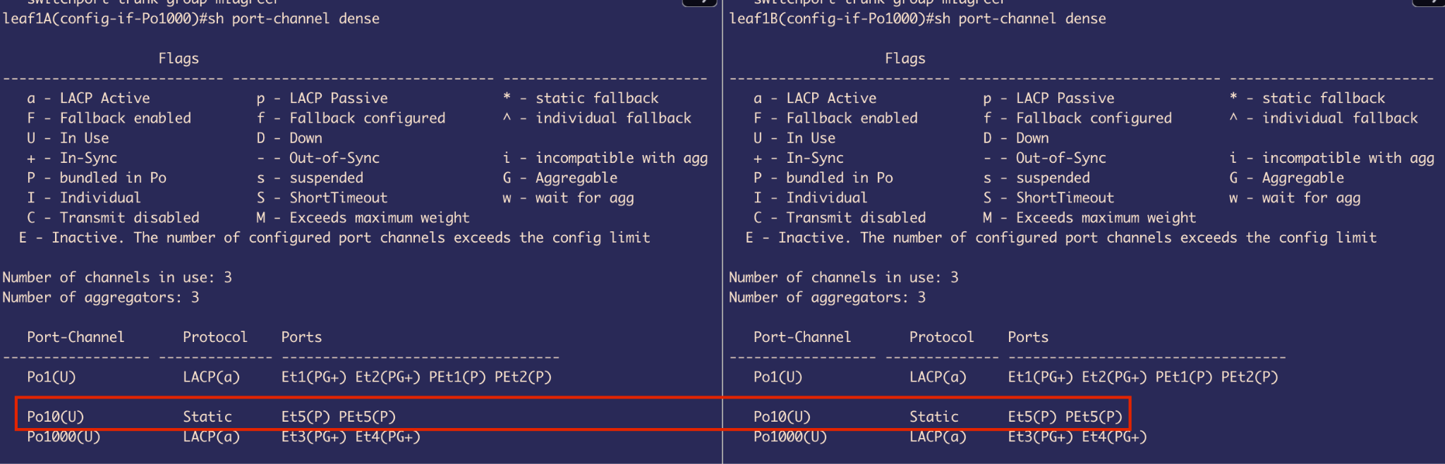 Figure 17: Routing table on Spine1 showing connected routes
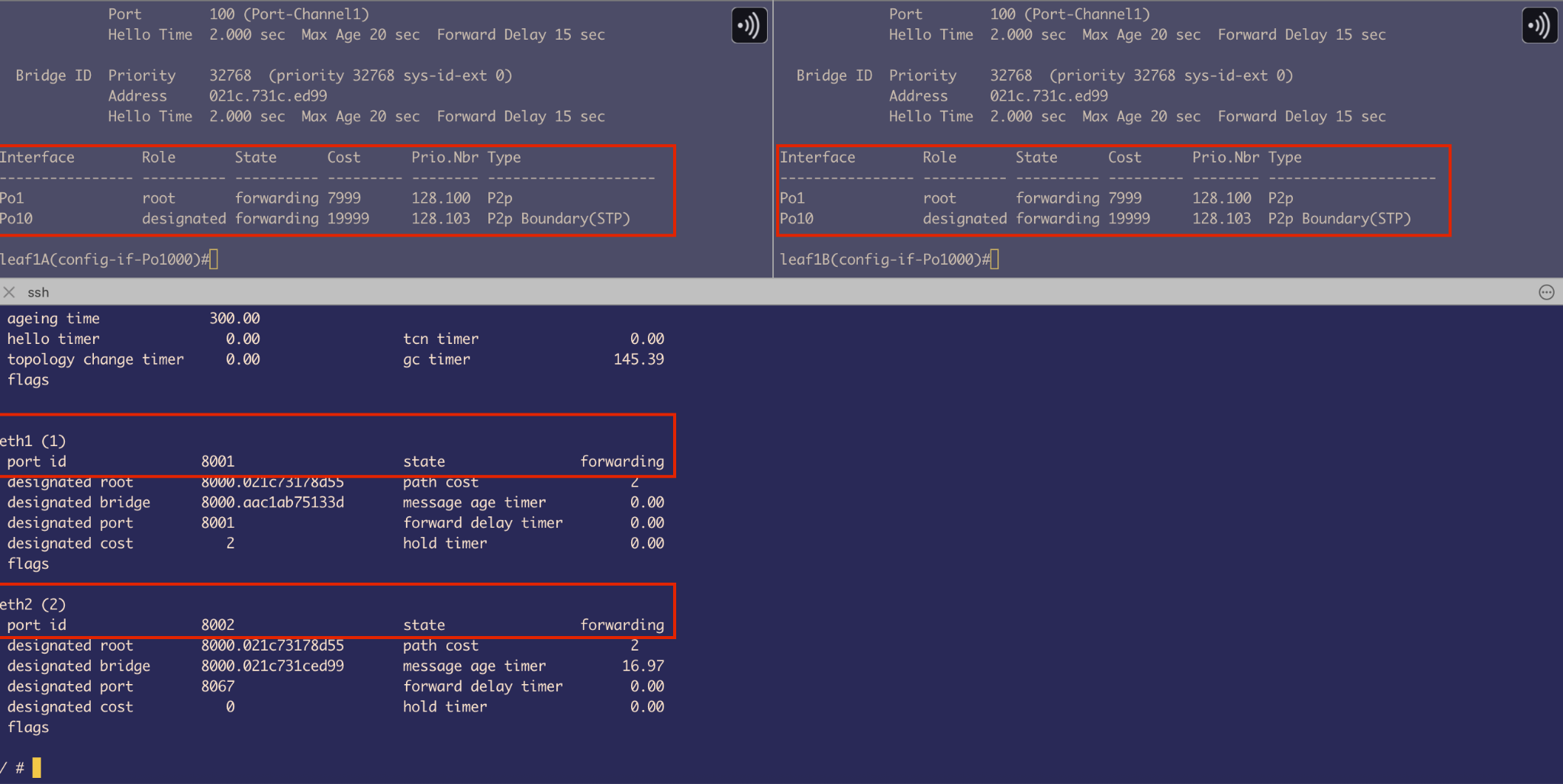 Figure 18: Routing table on Spine2 showing connected routes
Goal: Provide a single IP address that the host can use as its next hop for inter-VLAN routing. This also serves as a Layer 3 redundancy mechanism—if one MLAG peer switch goes down, the host can still reach the spines using the same IP address, ensuring uninterrupted traffic forwarding.
VARP Implementation:
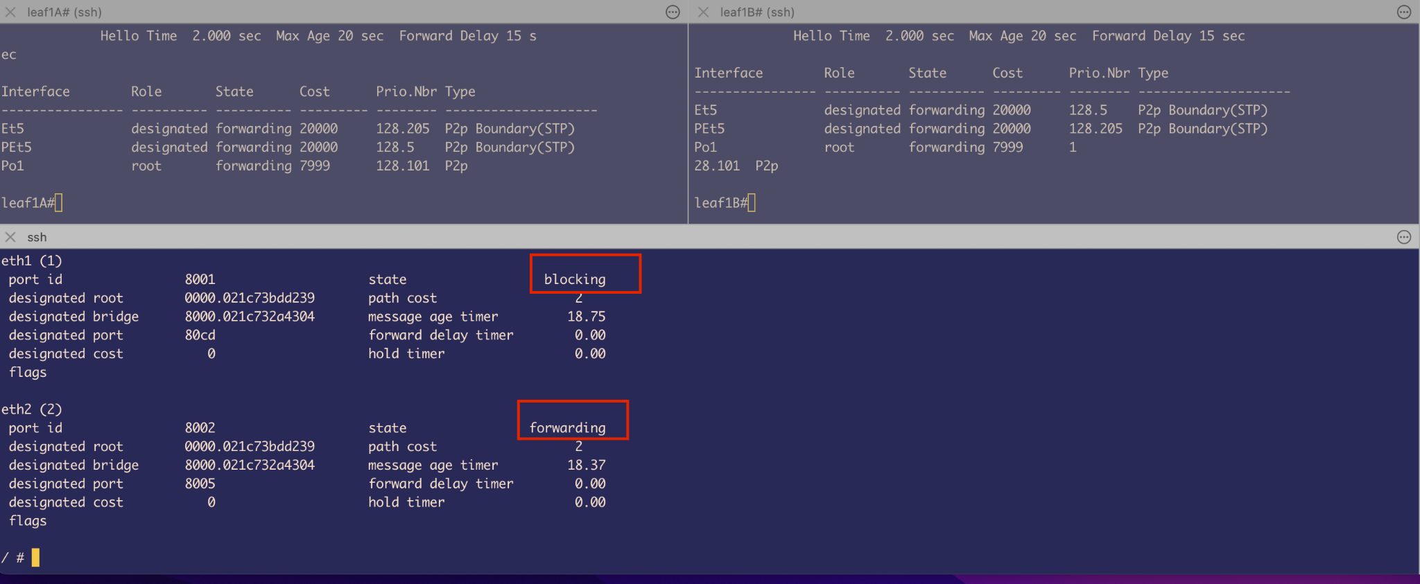 Figure 19: VARP virtual router configuration on Spine1
 Figure 20: VARP virtual router configuration on Spine2
- A virtual IP address is configured on each SVI (e.g., VLAN 10, VLAN 20)
- A shared virtual MAC address (e.g.,
baba.baba.baba) is assigned - This MAC address is locally administered (with the Local admin. bit set to 1)
- It is shared across both MLAG peer switches
Important Note: Using the same virtual MAC address across different VLANs is valid because each VLAN represents a separate broadcast domain. Therefore, assigning the same Virtual MAC for Virtual IPs in SVI interfaces for ARP resolution in VLAN 10 and VLAN 20 does not cause a conflict.
2. Service Leaf and Compute Leaf Configuration for Transparent Bridging
First, the Leaf switches are configured to be in MLAG similarly to the spine switches to provide L2 redundancy.
MLAG Status - Leaf 1A and Leaf 1B
Both are connected similarly to Spine MLAG peers, with:
- Port-channel 1000
- VLAN 4094 with same peer IP (different broadcast domain so IPs are reused)
 Figure 21: MLAG status on Leaf1A
 Figure 22: MLAG status on Leaf1B
MLAG Status - Leaf 2A and Leaf 2B
Both are connected similarly with the same configuration pattern.
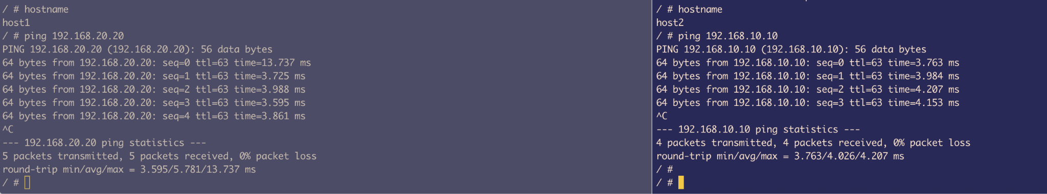 Figure 23: MLAG status on Leaf2A
 Figure 24: MLAG status on Leaf2B
VLAN Configuration
Leaf 1A and 1B:
- Configured VLAN 10
- Port-channel 1: Trunk port connected to uplink spines
- Port-channel 10: Access port that connects to Host
- Port-channel 1000: For MLAG
- VLAN 1: Native VLAN by default on all switches
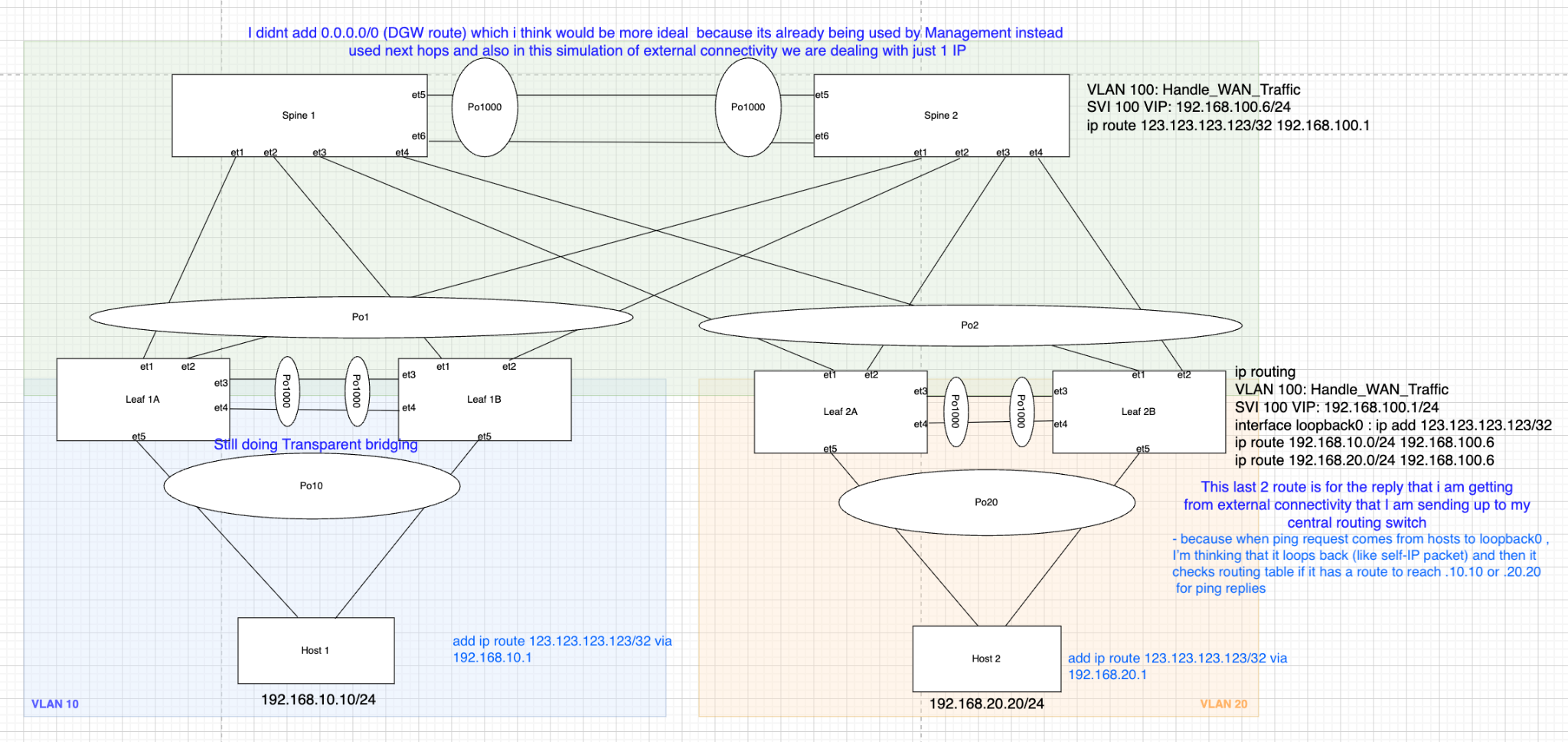 Figure 25: VLAN configuration on Leaf1A
 Figure 26: VLAN configuration on Leaf1B
Leaf 2A and 2B:
- VLAN 20: Used to carry traffic from Host through Port-channel 20
- Port-channel 2: Trunk port to carry traffic to uplink Spines
- VLAN 4094: For MLAG peer communication
- Port-channel 20: Access Port
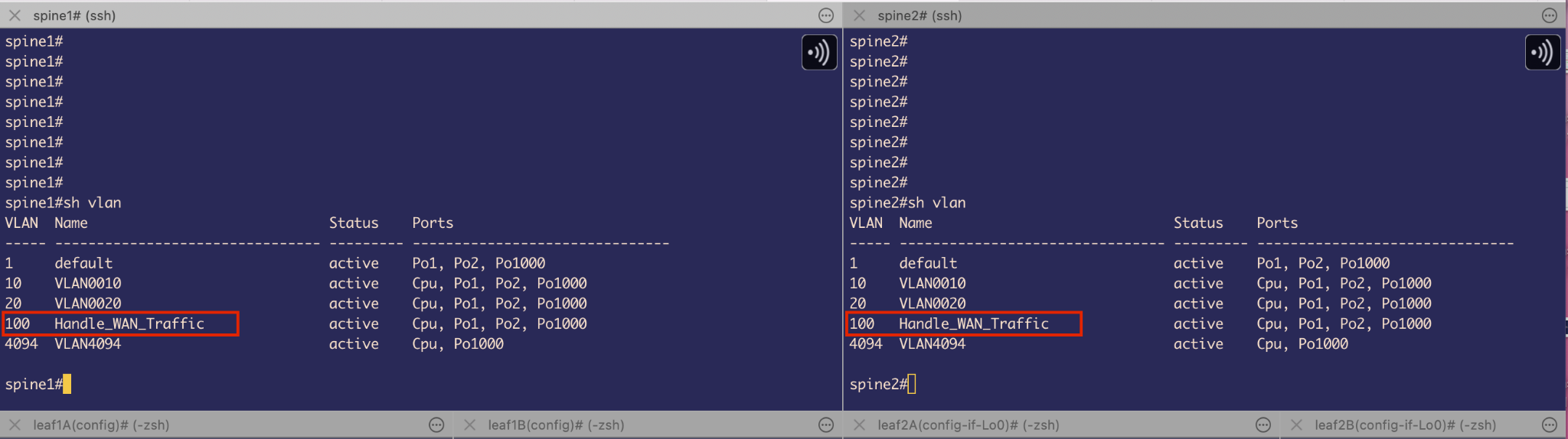 Figure 27: VLAN configuration on Leaf2A
 Figure 28: VLAN configuration on Leaf2B
Design Limitations and Resolution
One important detail in our setup is that Port-Channel10 on both Leaf1A and Leaf1B is configured in static mode instead of using LACP (Link Aggregation Control Protocol) in active mode.
Why the limitation?
Normally, LACP negotiates and syncs link state automatically between connected interfaces, but we hit a limitation on our host containers: the Alpine Linux containers didn’t support NIC bonding, as the necessary kernel bonding module wasn’t available.
NIC bonding is conceptually similar to port-channels on network switches—it combines multiple physical interfaces into one logical interface. Since Docker containers typically share the host kernel, and Docker restricts kernel module loading, we couldn’t enable bonding inside the containers.
Problems encountered:
The host couldn’t understand or respond to LACP packets - Since it’s just bridging Ethernet frames and not running LACP, LACP negotiation fails. So, the interfaces never bundle up and remain DOWN.
Bridging BPDUs across links creates a logical loop - If the MLAG primary (e.g., Leaf1A) sends a BPDU, the host bridges it across to its second interface connected to Leaf1B. Leaf1B then receives its peer’s BPDU as if it came from another switch. This looks like a Layer 2 loop, so the MLAG Leaf switch puts its port-channel 10 into a blocking state to prevent a loop.
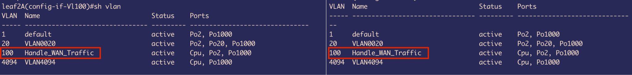 Figure 29: Port-channel configuration on Leaf1A showing static mode with LACP fallback
 Figure 30: Port-channel configuration on Leaf1B
Solution Attempt:
- To fix the first issue, we used static port-channels on the leaf switches instead of relying on LACP
- For the second issue, we enabled STP on the host bridge to force it to participate in spanning tree
This way, the host bridge processes incoming BPDUs and sends its own modified BPDU (changed Bridge ID) out the second interface. This prevents the MLAG peer from seeing its own BPDU.
However, this workaround introduces another subtle problem:
- The host sees both uplinks as connecting to different switches, so it treats one as Root Port and the other as a P2P edge Port (because it never got a BPDU from 2nd peer) or a Boundary (STP) - this terminology is used by old flavor of STP, both in forwarding state
- If Spine1 is the root bridge, the BPDU from Leaf1A (which received it from Spine1) arrives on eth1 of the host, and eth1 becomes the Root Port
- The host bridge modifies and sends out BPDUs on eth2 (to Leaf1B), which never received any BPDU from other peer MLAG switch
This behavior breaks MLAG assumptions and creates a forwarding L2 loop.
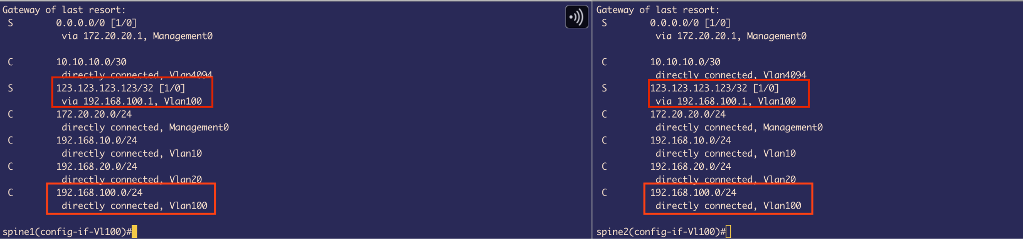 Figure 31: Spanning Tree showing both ports in forwarding state creating a loop
Port-channels were meant to increase bandwidth (which gets halved because of STP) without having L2 loops. However, here on the Leaf side we have a port-channel and on the other side we have a not-ideal situation which results in a L2 Loop as all are forwarding.
Quick Fix
Remove the Port-channel on the Leaf side that faces Host containers.
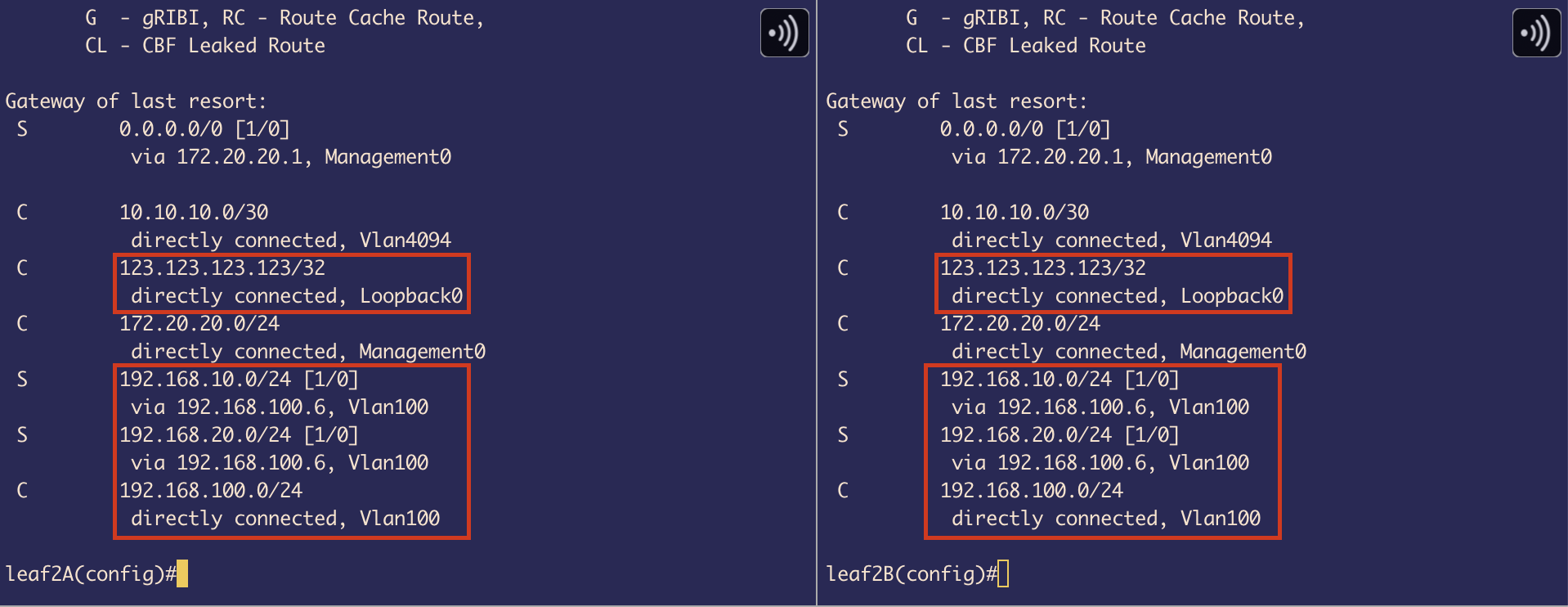 Figure 32: Spanning Tree after removing port-channel - one interface in blocking state
After removing the port-channels:
- The MLAG leaf switch thinks there are 2 switches downlink
- It sends BPDU from both sides with the same bridge ID
- The bridge on Host receives it from both sides and sets 1 interface to blocking state as it identifies that there is a loop
- It is getting the same BPDU from MLAG leaf switches from both sides
Trade-off: We now have less bandwidth – Half of the original.
3. Host Side Configuration
On Host side we configured 2 things:
- Setup bridging using a Linux command
brctl:- Enable STP
- Provide an IPv4 address
- Make sure the new Bridge link is UP and running
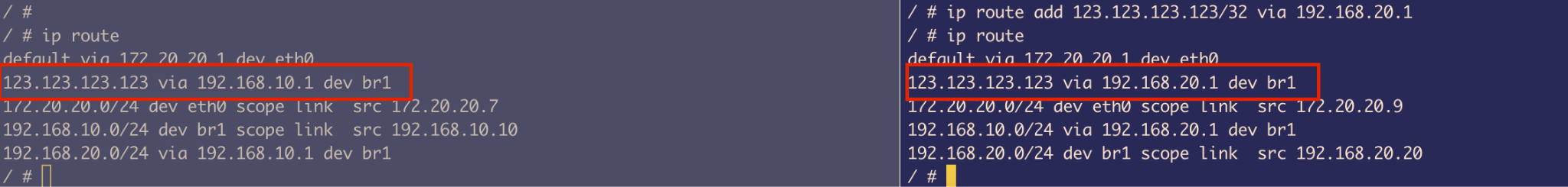 Figure 33: Bridge configuration on Host1
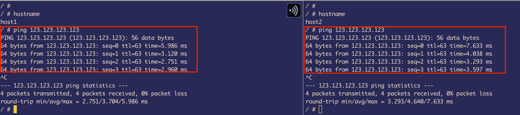 Figure 34: Bridge configuration on Host2
- Configure a Next hop to Spine’s SVI IP:
- Our Spine will be handling routing
- We are not going to configure the default gateway as it’s already taken by Management IP
- If we take that it will result in disconnection to the outside world
Result: We have successfully made all necessary configuration for the 2 hosts that are on different subnets and different VLANs to talk to each other.
Simple simulation test: Pinging from Host-to-Host - Testing inter-VLAN routing through the spine switches.
ARP Cache Verification: The arp cache got entries with Next hops’s IPs resolved to their Virtual MACs that we configured on Spines, confirming VARP is working correctly.
Simulate “External” Connectivity on Service Leafs
To complete the last part of the project with limited resources, we need to make a few tweaks to the existing switch configuration.
Overview
To simulate external connectivity, we use a loopback interface on the service leaf with a random IP address (123.123.123.123/32 in this case).
In a typical production setup, this would usually represent a firewall connected to the service leaf, providing access to the WAN (external world).
However, in our lab environment, we will not be using any actual WAN subnets (instead, exactly 1 external IP) or external firewalls/devices. Instead, the service leaf will act as a border device (border between our internal LAN and the simulated WAN represented by the loopback IP).
Configuration Steps
1. Configure External IP on Service Leaf
We use a Loopback interface for the external IP. The reason we use a loopback is that it behaves like a self-IP packet. Once the ping request reaches this loopback IP, the service leaf needs to generate a reply. Therefore, we also need to ensure that proper return routes are in place so the response can be routed back to the original host.
Important: We are using a /32 mask for the external connectivity IP. This means it is a host route, which implies that traffic will be routed only to this single specific destination — 123.123.123.123 in our case — and not to a wider subnet or range of addresses.
2. Create Dedicated VLAN 100 for WAN Traffic
I wanted to ensure network traffic separation for WAN (external connectivity) traffic. To achieve this, I created a dedicated VLAN 100 specifically for carrying packets destined for the WAN.
Where to define VLAN 100?
By carefully analyzing the packet flow in our topology, we can see that the only switches that have full route visibility to reach the host devices are the Spine MLAG switches.
Since our goal is for the hosts to reach the external IP (via the service leaf), and the Spines are responsible for routing between internal VLANs and the external destination, it makes the most sense to define and extend VLAN 100 on the Spine switches. This allows them to forward traffic to the service leaf over a dedicated path for WAN-bound traffic.
3. Configure SVIs on VLAN 100 (Spines)
I configured SVIs with virtual IPs on VLAN 100 on both Spine switches to provide Layer 3 redundancy for receiving the response WAN traffic from service Leaf.
4. Port-Channel Configuration
There’s no need to modify Port-Channel 2 on the Spine switches, since it is already configured as a trunk port. This means it can automatically carry traffic for VLAN 100, along with any other allowed VLANs.
5. Configure VLAN 100 on Service Leaf
The next best place to configure VLAN 100 is on the Service Leaf. Since the external IP (123.123.123.123/32) is assigned to a loopback interface on this switch, we ultimately need routing to be in place so that the traffic arriving from the Spine can reach this IP.
To enable that, we must:
- Configure a VLAN 100 SVI on the Service Leaf
- Enable IP routing
This allows the Spine to forward packets over this Layer 3 link. The Service Leaf will then route the traffic internally to the loopback interface, completing the simulated external connectivity and also, for sending response back to spine.
Setting Up Routes
1. On Spine
We have 2 important routes:
Connected Route for VLAN 100 subnet: When we created SVI 100 and assigned IP address, this made spine realize that it has a route for that subnet on VLAN 100
Static Route to External IP: We created a Static route that tells Spine where to go (next hop) if it wants to send traffic to an external IP:
ip route 123.123.123.123/32 192.168.100.1
We used /32 as it’s an exact host that we are trying to reach (external connectivity).
2. On Service Leaf (switches 2A and 2B)
On service Leaf, we have to think in terms of 2-way communication, because once the ping requests reaches from host to this Leaf, it has to send ping replies back to hosts. And also 1 point to keep in mind, that our Spines are the only ones that know the routes to Hosts.
So, we defined 2 routes for each host as they belong to different subnets & VLANs:
ip route 192.168.10.0/24 via 192.168.100.6
ip route 192.168.20.0/24 via 192.168.100.6
Since we have created SVI and given IP address on VLAN100 and also assigned IP address on Loopback0 interface (external IP), we can see Connected routes in the routing table.
3. Host Routes
It’s important to remember that the hosts initially don’t know how to reach an external IP address. To solve this, we manually defined a static route on both hosts, specifying the Spine switch as the next hop.
This is because the Spine acts as the centralized router in this topology, handling all inter-VLAN routing as well as routing traffic toward the external destination via VLAN 100.
Host’s Reachability Tests
I used ping commands to test the reachability of each host.
Observation: We can also conclude that traffic is passing through the Spine switches because the TTL (Time to Live) value is 63.
By default, Linux sets the TTL for ICMP echo requests to 64. Since the packet is traversing one routing hop (the Spine) before reaching the destination (Service Leaf), the TTL is decremented by 1, resulting in 63 when it reaches the host and replies.
This confirms that the traffic is being routed via the Spines. (We can also use traceroute for verification.)
Traffic Flow Summarization
Host 1 (192.168.10.10/24) / Host 2 (192.168.20.20/24) to External Connectivity (123.123.123.123/32)
Detailed Flow:
If Host 1 pings 123.123.123.123:
- The host realizes it’s on a different network, so it checks its routing table to see if any route is defined to reach that network
- Since we’ve already defined a next hop to the spine, it matches the IP address of SVI 10 VIP on the spine using the longest prefix match
- Then it checks if it has an ARP entry for that IP
- If it doesn’t have an ARP entry in its cache, it sends an ARP request (broadcast traffic), and the spine sends an ARP reply (unicast traffic)
- Now it has the spine’s VIP + MAC address of SVI 10
- Then it checks which interface the MAC address is behind using the MAC/CAM table
- Now that it has everything, it sends an ICMP echo request packet to the spine using VLAN 10
- Leaf 1A and 1B are doing transparent bridging, so this packet is a data plane packet for the switch, and the ASIC just forwards it to the uplink spine switches
At the Spine:
- Since the destination MAC of the packet is the same as the MAC address of SVI 10, it triggers routing
- It checks the destination IP (123.123.123.123) and looks in its routing table to see if it has a route
- It does — via the next hop 192.168.100.1 (SVI 100 VIP of Leaf 2A & 2B)
- Again, it checks if it has ARP; if not, it sends ARP requests and gets back an ARP reply
- Then it checks its MAC table to know which interface that MAC is behind — it’s behind Po2
- So it uses that to send traffic to the downlink switch (Leaf 2A & 2B MLAG) through VLAN 100
At the Service Leaf:
- The ICMP packet received by the service leaf has the same destination MAC as the MAC address of SVI 100, which triggers routing
- It checks the routing table to see if it has a route, and it does — the loopback IP is defined as an exact host route (/32)
- It performs a self-IP packet and creates an ICMP reply
Return Path:
- Since it has to send the traffic back, it checks its routing table to see if it has any routes to 192.168.10.10 (Host 1)
- Yes, it has a route allocated for 192.168.10.0/24, which goes through VLAN 100 to the SVI VIP of the spine (192.168.100.6)
- It sends the traffic back to the spine
- The spine has the route defined for the host on VLAN 10 as a connected route, so here the spine creates an ARP request — but this time directly for Host 1 — and tries to resolve its MAC address
- After that, it sends the ICMP reply down to Leaf 1A & 1B through the VLAN 10 trunk port
- The leaf switches perform transparent bridging, and the ASIC forwards it downlink to Host 1
Traffic Trombone for Host 2 (192.168.20.20/24)
Traffic tromboning happens on Host 2 because traffic is routed through a distant centralized point (spine, in this case) and taking a less efficient path and even has an overlapping path with the actual Service leaf that has an external connectivity.
Just for Host 2, it crosses Leaf 2A&B to get to Spine where it gets routed again back to Leaf 2A&B, where it gets routed again to reach the external IP.
This also causes more latency for the packet to reach its destination.
Topics Learned from the Project
Throughout the project, I gained practical and in-depth knowledge across multiple areas of networking and system design. Here are the key topics and concepts I explored:
ASIC and Control Plane Interaction
Understood how modern switches use ASICs (Application-Specific Integrated Circuits) to forward data plane traffic at line rate using hardware-accelerated paths. And understood what unicast and multicast pipelines inside ASIC are and how it uses multicast replication engine to send multiple copies of packet in case of BUM traffic, while control plane traffic (e.g., routing protocols, ARP requests) is punted to the CPU for processing. This separation ensures efficient packet forwarding and proper handling of control traffic.
Hardware Tables in the Data Plane
Learned about critical hardware tables such as:
- FIB (Forwarding Information Base): Hardware-copy of the routing table
- L2 adjacency table: Hardware-copy of the ARP table
These tables are utilized by the ASIC to make faster forwarding decisions.
Spanning Tree Protocol (STP)
Gained a solid understanding of how STP prevents Layer 2 loops by:
- Electing a Root Bridge
- Strategically placing interfaces into Forwarding or Blocking states
Studied how BPDU (Bridge Protocol Data Units) are generated and processed, and how Root Ports, Designated Ports, and Blocked Ports are determined.
Also explored various STP flavors:
- RSTP (Rapid Spanning Tree Protocol)
- MSTP (Multiple Spanning Tree Protocol)
- PVST+ (Per VLAN Spanning Tree Plus – Cisco proprietary)
Port-Channels and Link Aggregation
Learned how Port-Channels (LAGs) are used to:
- Increase bandwidth
- Eliminate STP-blocked links by bundling multiple physical links into a single logical interface
Explored how hash-based load balancing determines traffic distribution across links and how Port-Channels help maintain loop-free redundancy.
VLANs and SVIs
Understood how:
- VLANs (Virtual LANs) segment a LAN into multiple broadcast domains logically
- SVIs (Switched Virtual Interfaces) are configured on switches to enable Layer 3 routing between VLANs
MLAG (Multi-Chassis Link Aggregation)
Studied MLAG, which allows two switches to appear as a single logical switch to connected devices. Explored how LACP (Link Aggregation Control Protocol) uses the same system ID across MLAG peers to make uplink and downlink devices believe they’re connected to a single switch.
Transparent Bridging
Explored how transparent bridges operate at Layer 2 by forwarding packets without modifying them, relying on MAC address learning. Understood the forwarding logic from ingress to egress without IP layer interaction.
Inter-VLAN Routing and Packet Lifecycle
Learned how switches perform inter-VLAN routing using SVIs (Switched Virtual Interfaces) on Layer 3-capable devices, and how they leverage routing and ARP tables to resolve next-hop information.
Gained a solid understanding of the “Day in the Life of a Packet” in both centralized IRB (Integrated Routing and Bridging) and decentralized IRB designs.
Packet Processing Sequence:
- Routing table lookup to verify if a valid route exists
- ARP table check to resolve the MAC address of the next-hop IP
- MAC address table lookup to identify the egress interface associated with that MAC
Based on this sequence — routing table → ARP table → MAC table — the switch makes a forwarding decision and routes the packet accordingly. This layered lookup process was essential in understanding how routing actually works under the hood and proved extremely useful during troubleshooting.
Troubleshooting Tools
Became proficient in using tools like:
- tcpdump: For packet capture
- ethxmit: For manually generating packets
These were really useful in verifying network behavior, diagnosing issues, and validating our understanding of traffic flows. Also setting up CPU mirroring was helpful to get copies of Data plane packet that ASIC was forwarding.
Docker, YAML, and ContainerLab Setup
Gained hands-on experience in using Docker and ContainerLab to simulate complex network topologies. Understood how YAML files are used to define container configurations and how containers simulate switches and hosts using cEOS and Linux /images.
Port-forwarding
Also learned about port forwarding in the context of Docker container deployment. This was particularly useful when binding the container’s internal SSH service (port 22) to a specific port on the host machine (e.g., port 2222).
NIC Bonding and Bridging on Hosts
Explored:
- NIC bonding (similar to switch Port-Channels)
- Linux bridging to create redundancy and logical interface aggregation on host systems
Also learned about kernel module limitations inside Docker containers and the impact on bonding support.
LLDP (Link Layer Discovery Protocol)
Understood how LLDP is used for device discovery and troubleshooting by advertising identity, capabilities, and interface details between connected devices—especially useful in verifying physical and logical topology.
ACL (Access Control List)
Also learnt about what is Access Control List and how it is used on receiving (inbound) interfaces to filter packets. And how it’s used to protect control planes.
YAML File Used to Create the Topology in ContainerLab
name: branislav-DCU2025-abhinav

topology:
  nodes:
    spine1:
      kind: ceos
      image: ceos:4.32.2F
      ports:
        - 10016:22/tcp

    spine2:
      kind: ceos
      image: ceos:4.32.2F
      ports:
        - 10017:22/tcp

    leaf1A:
      kind: ceos
      image: ceos:4.32.2F
      ports:
        - 10018:22/tcp

    leaf2A:
      kind: ceos
      image: ceos:4.32.2F
      ports:
        - 10019:22/tcp

    leaf1B:
      kind: ceos
      image: ceos:4.32.2F
      ports:
        - 10020:22/tcp

    leaf2B:
      kind: ceos
      image: ceos:4.32.2F
      ports:
        - 10021:22/tcp

    host1:
      kind: linux
      image: alpine
      ports:
        - 10022:22/tcp

    host2:
      kind: linux
      image: alpine
      ports:
        - 10023:22/tcp

  links:
    - endpoints:
        - spine1:eth1
        - leaf1A:eth1

    - endpoints:
        - spine2:eth1
        - leaf1A:eth2

    - endpoints:
        - leaf1B:eth3
        - leaf1A:eth3

    - endpoints:
        - leaf1A:eth4
        - leaf1B:eth4

    - endpoints:
        - spine1:eth2
        - leaf1B:eth1

    - endpoints:
        - spine2:eth2
        - leaf1B:eth2

    - endpoints:
        - spine1:eth3
        - leaf2A:eth1

    - endpoints:
        - spine2:eth3
        - leaf2A:eth2

    - endpoints:
        - spine1:eth4
        - leaf2B:eth1

    - endpoints:
        - spine2:eth4
        - leaf2B:eth2

    - endpoints:
        - leaf2B:eth3
        - leaf2A:eth3

    - endpoints:
        - leaf2A:eth4
        - leaf2B:eth4

    - endpoints:
        - leaf1A:eth5
        - host1:eth1

    - endpoints:
        - leaf1B:eth5
        - host1:eth2

    - endpoints:
        - leaf2A:eth5
        - host2:eth1

    - endpoints:
        - leaf2B:eth5
        - host2:eth2

    - endpoints:
        - spine2:eth5
        - spine1:eth5

    - endpoints:
        - spine1:eth6
        - spine2:eth6
Summary
This project provided comprehensive hands-on experience with:
- Modern data center network design patterns (Leaf-Spine)
- Layer 2 and Layer 3 redundancy mechanisms (MLAG, VARP)
- Inter-VLAN routing and external connectivity simulation
- Containerized network emulation using Docker and ContainerLab
- In-depth packet flow analysis and troubleshooting
The project successfully demonstrated a working L2/L3 network with redundancy at multiple layers, though trade-offs were made due to container limitations, particularly around port-channel configurations at the host level.
Key Achievements:
- Successfully configured MLAG on all switch pairs for L2 redundancy
- Implemented VARP for L3 redundancy and active-active gateway forwarding
- Achieved inter-VLAN routing between hosts on different subnets
- Simulated external connectivity using loopback interfaces and static routing
- Overcame Docker container limitations with creative workarounds
- Gained deep understanding of packet forwarding, STP, and routing decisions